
Intelligent control dragging device of combined permanent magnet variable-frequency synchronous oil pumping unit

A technology of intelligent control and dragging device, which is applied in electromechanical devices, synchronous motors with stationary armatures and rotating magnets, electrical program control, etc., can solve the lack of real-time remote transmission of control cabinet detection data, and the disconnection between motors and intelligent digitalization , Inability to effectively use electrical parameter control and other issues to achieve the effects of reducing stator copper consumption, small motor current, and low slippage during operation

Pending Publication Date: 2020-07-24
大庆采艺技术开发有限公司
View PDF0 Cites 0 Cited by
  • Summary
  • Abstract
  • Description
  • Claims
  • Application Information

AI Technical Summary

Problems solved by technology

[0002] At present, the drag device, motor, and digital control box used in the oil field are composed of independent work. The disadvantage is that the drag device and the motor have rotor reactive power consumption, which cannot better realize energy saving, and most of them are asynchronous motors with low efficiency. , the digital control box also works independently and relies on various sensors to realize numerical control, which cannot effectively use electrical parameter control, resulting in the phenomenon that various parts are disordered and the performance is not comprehensive enough
[0005] Moreover, the existing technology is not equipped with an intelligent control system, the motor and intelligent digitalization are disconnected, and the lack of a control cabinet to realize the real-time remote transmission of the detection data of the pumping unit through the wireless network, the customer cannot use the PC or mobile APP to connect to the server anytime and anywhere. Intelligent control system for condition monitoring of each equipment

Method used


Image

  • Intelligent control dragging device of combined permanent magnet variable-frequency synchronous oil pumping unit
  • Intelligent control dragging device of combined permanent magnet variable-frequency synchronous oil pumping unit
  • Intelligent control dragging device of combined permanent magnet variable-frequency synchronous oil pumping unit

Examples


Embodiment 1

[0042] Such as figure 1 As shown, the variable frequency speed regulating permanent magnet synchronous motor and the pumping unit are connected through a belt, and the intelligent control system remotely controls the frequency conversion speed regulating permanent magnet synchronous motor and transmits the detection data of the pumping unit in real time through the wireless network;

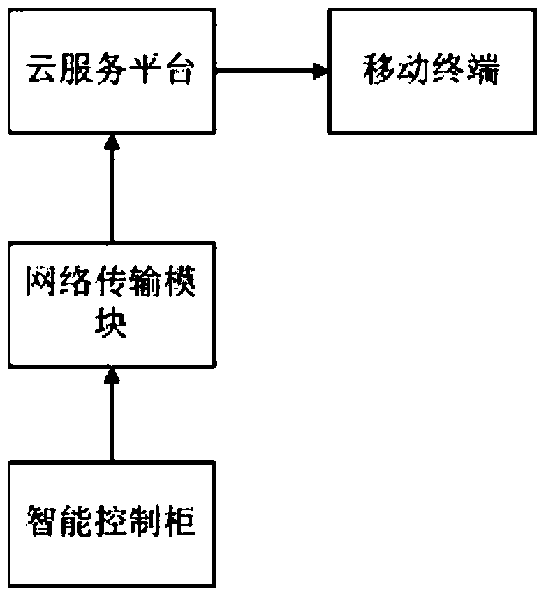
[0043] Such as figure 2 As shown, the intelligent control system includes a network transmission module, a cloud service platform, a mobile terminal and an intelligent control cabinet. The intelligent control cabinet is connected to the cloud service platform through the network transmission module, and the output terminal of the cloud service platform is connected to the input terminal of the mobile terminal.

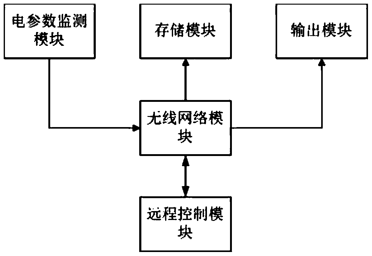
[0044] Such as image 3 As shown, the intelligent control cabinet includes an electrical parameter monitoring module, a remote control module, a storage module, an output module and a w...

Embodiment 2

[0049] A manufacturing method of a combined permanent magnet variable frequency synchronous pumping unit intelligent control drive motor driving device:

[0050] 1. Special technology for "one-knife-through" processing of the casing:

[0051] The casing is the core component of the motor support system. The most basic requirement for the casing is to have sufficient mechanical strength, dimensional accuracy and coaxiality accuracy. The mechanical strength is guaranteed by the material, structure and thickness of the casing, and the dimensional accuracy is also guaranteed. It is easy to guarantee, but the coaxiality accuracy is very important. If the coaxiality accuracy cannot be guaranteed, it will cause uneven air gap of the motor and affect the performance of the motor, and it will cause the stator and rotor of the motor to rub against each other, so that the motor cannot work normally and will be lost in advance. motor function.

[0052] In the prior art, the current gener...

Embodiment 3

[0075] In this embodiment, the driving part is composed of a permanent magnet variable frequency synchronous motor and a pulley, and the permanent magnet synchronous motor is mainly composed of a stator and a rotor. The rotor is mainly composed of rotor core, magnetic steel, and rotating shaft. The rotor core is composed of rotor punches and magnetic steel. The magnetic steel in the rotor core is arranged in a radial and tangential hybrid arrangement. After combination, it forms a squirrel-cage-free, magnetic Steel built-in hybrid rotor with no reactive power consumption. The stator adopts conventional stator core and stator winding. These two parts constitute the motor drive part capable of variable frequency rotation, the structure is shown in Figure 4 , Working principle: The rotor of the motor is equipped with magnetic steel. Due to the existence of the rotor magnetic steel, an air gap magnetic flux is formed inside the motor, and a three-phase stator current is generate...


PUM


Abstract

The invention provides an intelligent control dragging device of a combined permanent magnet variable-frequency synchronous oil pumping unit, and belongs to the technical field of special variable-frequency speed regulation permanent magnet synchronous motors for oil fields. According to the device, a motor is connected with an oil pumping unit through a belt; an intelligent control system can beused for locally controlling or remotely controlling a variable-frequency and variable-speed permanent magnet synchronous motor in real time through a wireless network and transmitting detection dataof the oil pumping unit, so that real-time remote transmission of detection data of the oil pumping unit is realized through a wireless network so as to achieve digital oil extraction work of an oil field; and a casing, an end cover, a shaft and a bearing form the supporting system of the motor, a stator coil, a stator iron core, a rotor iron core and magnetic steel form the circuit and magnetic circuit system of the motor, and the motor is enabled to continuously input power required by a load under the condition that three-phase current of the stator coil is given by a driver. The intelligent control dragging device is energy-saving, high in power factor, small in motor current, free of slip frequency in operation and stable in rotating speed, the temperature rise is 15-20 DEG C lower than that of an asynchronous motor, and the purposes of high efficiency and energy conservation are achieved.

Description

technical field [0001] The invention relates to a combined permanent-magnet variable-frequency synchronous pumping unit intelligent control drag device, which belongs to the field of special-purpose variable-frequency speed-regulating permanent-magnet synchronous motors for oilfields and the technical field of digital oilfield engineering. Background technique [0002] At present, the drag device, motor, and digital control box used in the oil field are composed of independent work. The disadvantage is that the drag device and the motor have rotor reactive power consumption, which cannot better realize energy saving, and most of them are asynchronous motors with low efficiency. , The digital control box also works independently and relies on various sensors to realize numerical control, which cannot effectively use electrical parameter control, resulting in the phenomenon that various parts are disordered and the performance is not comprehensive enough. [0003] With the rap...

Claims


Application Information

Patent Timeline
IPC IPC(8): H02K21/14H02K15/14H02K15/03H02K15/02H02K15/16G05B19/04
CPCG05B19/04H02K15/02H02K15/03H02K15/14H02K15/16H02K21/14
Inventor 荣洪涛马华东荣刚
Owner 大庆采艺技术开发有限公司
Learn More