Electrostatic separation device and process for removing solid particles in catalytic cracking slurry oil and slurry oil purification device
A technology of catalytic cracking oil slurry and electrostatic separation, which is applied in the petroleum industry, processing hydrocarbon oil, and refining through electric/magnetic fields, etc., can solve problems such as difficulty in normal and stable operation of the device, increase in the conductivity of the medium, and increase in the frequency of backwashing, etc. It can solve the effect of excessive current and frequent tripping of the device, increase the space of the settlement area, and avoid collision and anti-mixing.
- Summary
- Abstract
- Description
- Claims
- Application Information
AI Technical Summary
Problems solved by technology
Method used
Image
Examples
Embodiment 1
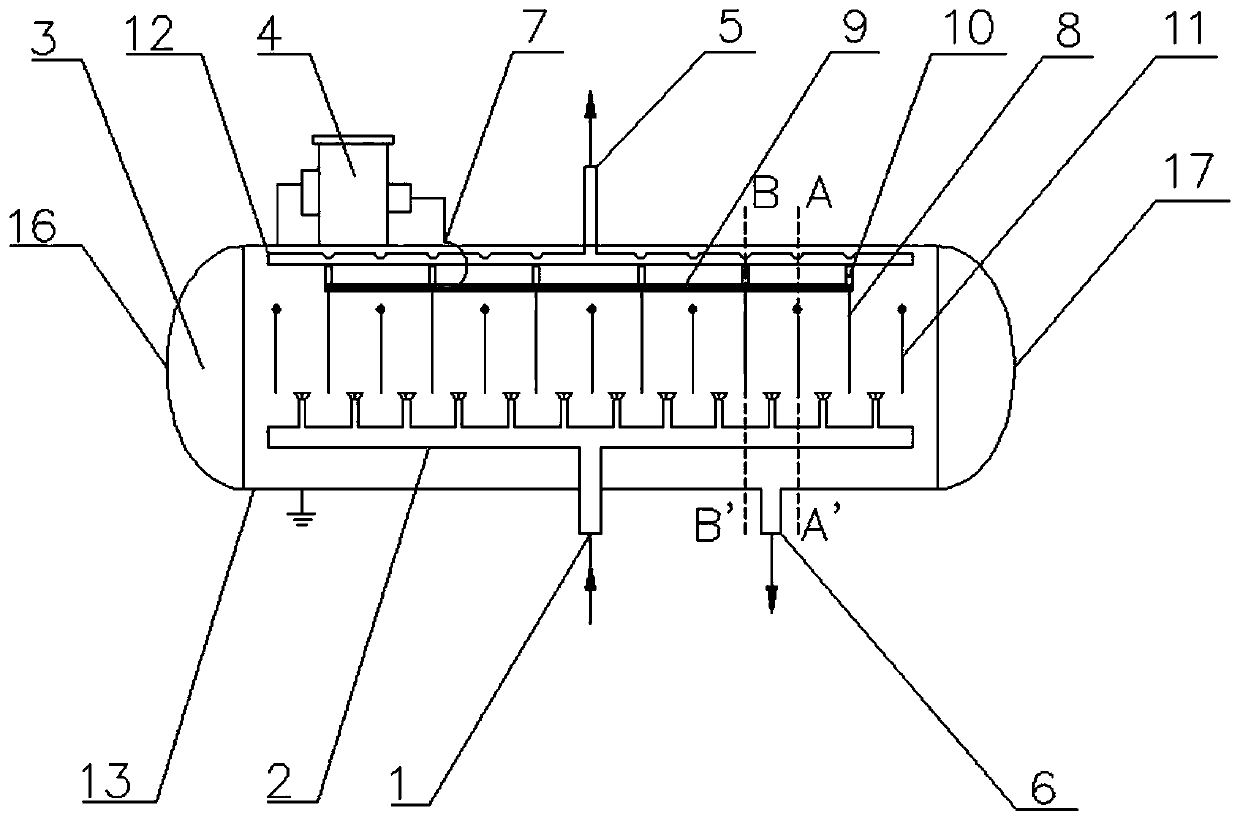
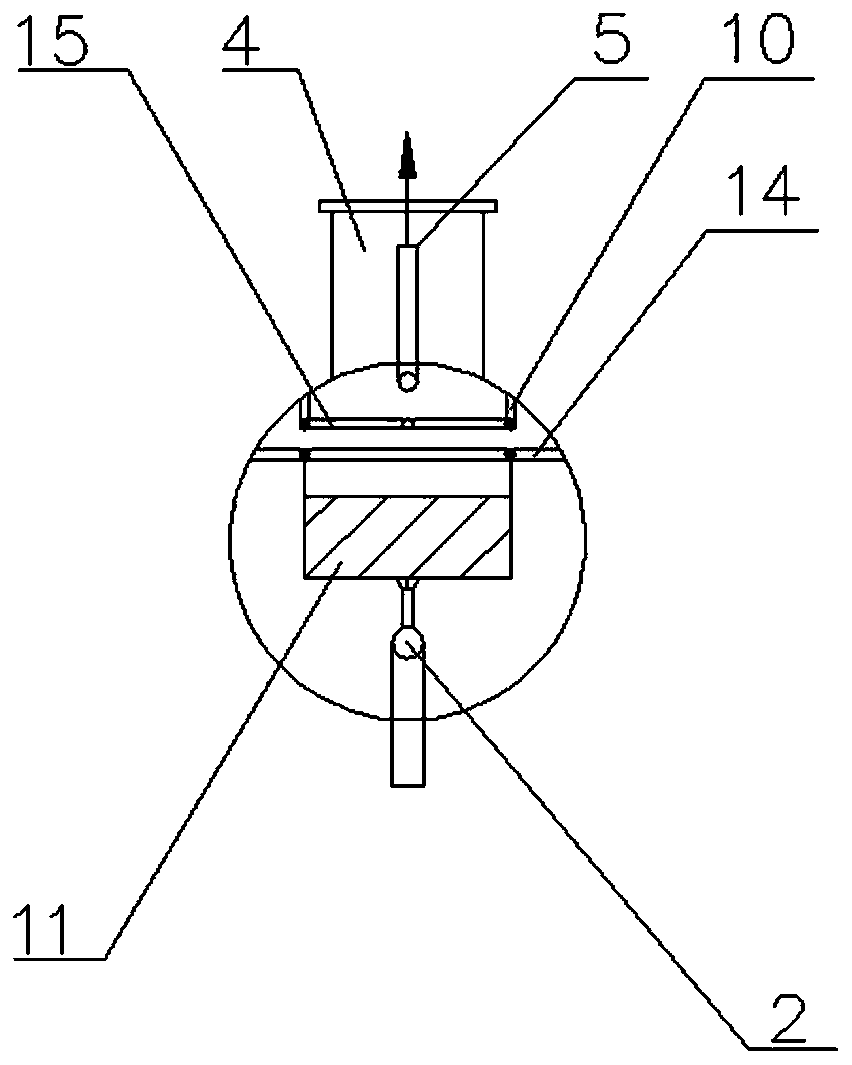
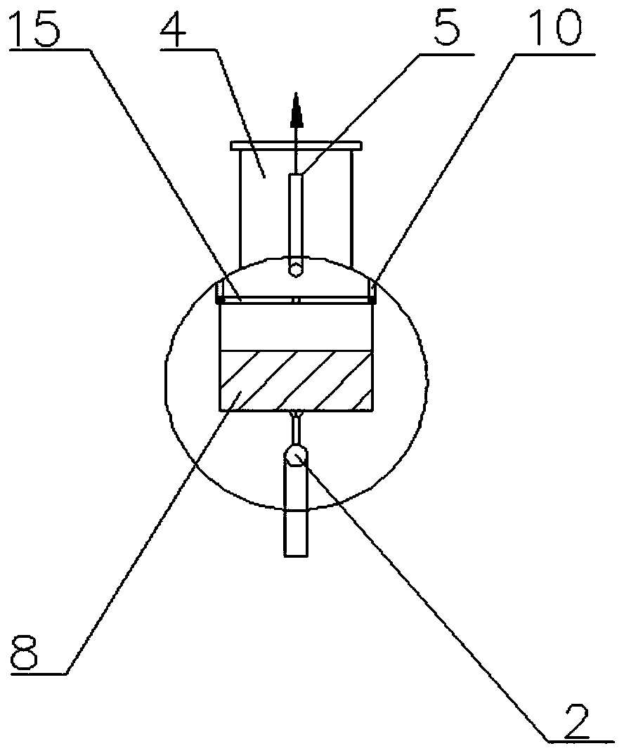
[0061] refer to figure 1 and figure 2 As shown, the present embodiment provides a catalytic cracking oil slurry electrostatic separation device, which includes an electrostatic separator 3, the electrostatic separator 3 is composed of a casing 13, a high voltage power supply 4, a raw material distributor 2, an electrostatic field area, and a left head 16 And right head 17 forms. The heated catalytic cracking oil slurry is evenly distributed in the electrostatic field area through the raw material distributor 2 to polarize the oil slurry, so that the solid particles gather and grow on the electrode plate, and are adsorbed on the electrode surface, and gravity sedimentation occurs, and then from the catalytic cracking Separation and removal from cracked oil slurry.
[0062] Specifically, refer to figure 1 and figure 2 As shown, the raw material enters the raw material distributor 2 through the raw material inlet 1 provided at the bottom of the shell 13, and the raw materia...
Embodiment 2
[0079] This embodiment provides an example of purifying heavy oil catalytic cracking oil slurry using the purification device shown in Embodiment 1.
[0080] The density of heavy oil catalytic cracking oil slurry in Refinery 1# is 1.0256g / cm 3 , the solid particle content is 2550μg / g, the oil slurry is heated to 160°C, and then enters the electrostatic separator for purification treatment. The electrostatic separation time is 60min, and the voltage is AC DC12000V. Sampling and analysis are carried out every 60min. The test results are shown in the table 1.
[0081] From the test results, after the catalytic oil slurry is purified, micron and submicron particles are removed, the solid particle removal rate exceeds 98%, and the solid particle content is ≤50μg / g, which meets the requirements of deep purification, and the oil The pulp recovery rate can reach 95%. In addition, the device can realize continuous and stable operation.
[0082] Table 1 The effect of electrostatic sep...
Embodiment 3
[0085] This embodiment provides an example of purifying heavy oil catalytic cracking oil slurry using the purification device shown in Embodiment 1.
[0086] The density of heavy oil catalytic cracking slurry in refinery 2# is 1.1359g / cm 3 , the solid particle content is 4230μg / g, the oil slurry is heated to 170°C, and then enters the electrostatic separator for purification treatment. The electrostatic separation time is 90min, and the voltage is DC13000V. Sampling and analysis are carried out every 90min. The test results are shown in Table 2 .
[0087] According to the test results, after the catalytic oil slurry is purified, the solid particle removal rate exceeds 99%, and the solid particle content is ≤20μg / g, which meets the requirements of deep purification, and the recovery rate of the oil slurry can reach 95%. In addition, the The device can realize continuous and stable operation.
[0088] Table 2 The effect of electrostatic separation and purification of 2# oil sl...
PUM
| Property | Measurement | Unit |
|---|---|---|
| density | aaaaa | aaaaa |
| density | aaaaa | aaaaa |
| density | aaaaa | aaaaa |
Abstract
Description
Claims
Application Information
 - R&D
- Intellectual Property
- Life Sciences
- Materials
- Tech Scout
- Unparalleled Data Quality
- Higher Quality Content
- 60% Fewer Hallucinations
Browse by: Latest US Patents, China's latest patents, Technical Efficacy Thesaurus, Application Domain, Technology Topic, Popular Technical Reports.
© 2025 PatSnap. All rights reserved.Legal|Privacy policy|Modern Slavery Act Transparency Statement|Sitemap|About US| Contact US: help@patsnap.com


