Automatic layered water taking system

A layered water intake and water intake tower technology, applied in water conservancy projects, artificial waterways, hydroelectric power generation, etc., can solve problems such as irrigation, adverse effects of aquatic organisms, complex operation of steel structure stacking doors, and influence of water temperature distribution in downstream river sections. Achieve the effects of strong functional scalability, reduced steel consumption, and reduced investment costs

Pending Publication Date: 2020-07-28
CHINA POWER CONSRTUCTION GRP GUIYANG SURVEY & DESIGN INST CO LTD
View PDF6 Cites 0 Cited by
  • Summary
  • Abstract
  • Description
  • Claims
  • Application Information

AI Technical Summary

Problems solved by technology

After the formation of large and medium-sized reservoirs, the water temperature in the reservoir area will be stratified, and the discharge of the water temperature in the middle and lower layers of the reservoir area will affect the water temperature distribution in the downstream river section, thus causing adverse effects on irrigation and aquatic organisms
At present, the water intake towers of domestic hydropower stations adopt the steel structure multi-section door leaf stacking beam door structure. The steel structure stacking beam door is a combination of multi-section door leaves. Hoisting section by section, the amount of steel used is large, and the investment is high

Method used


Image

  • Automatic layered water taking system
  • Automatic layered water taking system
  • Automatic layered water taking system

Examples


Embodiment Construction

[0023] The technical solution of the present invention is further described below in conjunction with the accompanying drawings, but the scope of protection is not limited to the description.

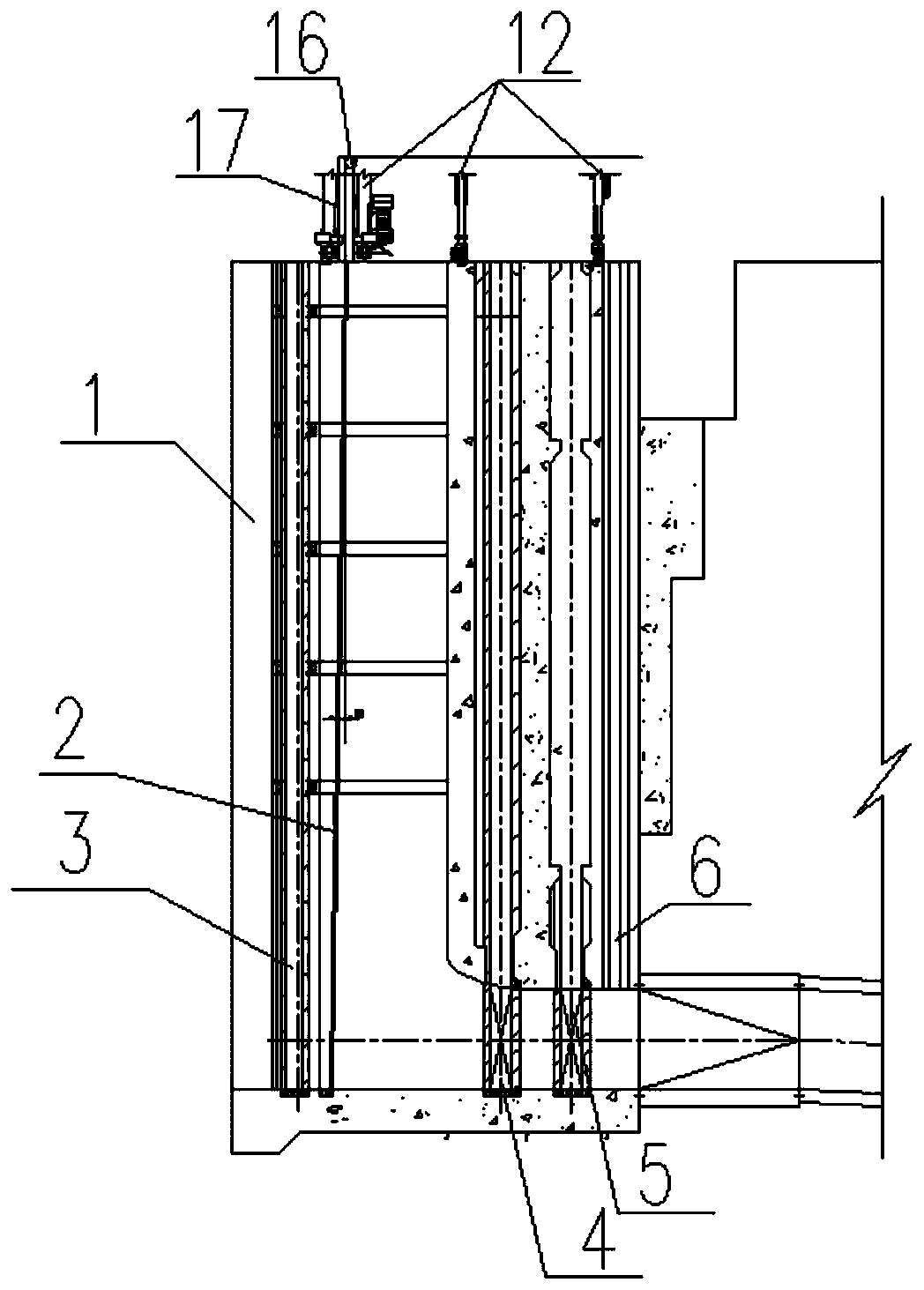
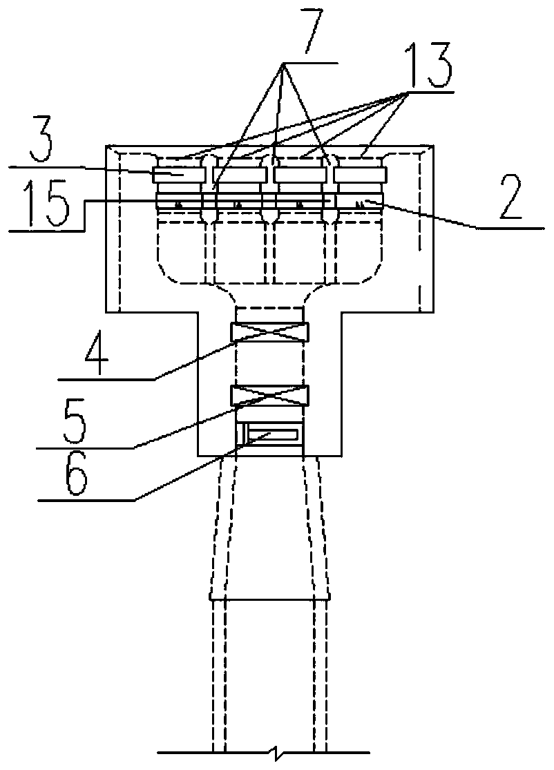
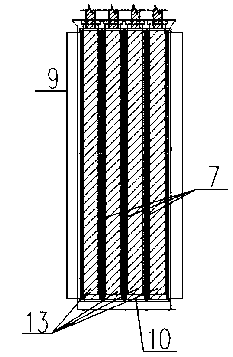
[0024] Such as Figure 1 to Figure 5 As shown, the present invention provides an automatic layered water intake system, which includes a rolling curtain 2, a water-permeable hanging cloth 11 and a water intake tower 1 deployed in the water flow channel. The water intake tower 1 faces the upstream side of the water flow. The water surface, the opposite side is the back water surface, the back water surface is connected with a curtain wall, the bottom of the curtain wall is equipped with an electromagnetic strip 10, the length direction of the electromagnetic strip 10 is the same as the width direction of the water flow channel, and a winch 12 is installed on the top of the curtain wall. One side of the hanging cloth 11 is wound on the outer peripheral surface of the reel, the other side ...


PUM


Abstract

The invention discloses an automatic layered water taking system. The automatic layered water taking system comprises roller blind curtains, water-permeable hanging cloths and a layered water taking tower. Electromagnetic blocks are correspondingly arranged at the two sides and the bottom of side blocks and fence blocks of the upstream face of the water taking tower. Winches, rollers and roller supports are mounted on the top of the water taking tower. The hanging cloths are wound around reels of the winches. The hanging cloths are hung on the upstream face of the water taking tower through the rollers. The hanging cloths are connected with the roller blind curtains through cylinders. Counterweight strips are fixedly bonded to the lower sides of the roller blind curtains. An iron flexiblematerial is attached to the two sides and the bottom of each roller blind curtain. The relative height of the electromagnetic block and flexible material arrangement positions relative to the portionbetween the bottoms of water channels is the same as the water taking elevation preset by a user. The electromagnetic blocks are independently communicated with a power source. The automatic layered water taking system has the beneficial effects that the water isolation range of the roller blind curtains is lowered to be below the water taking elevation preset by the user through the windable roller blind curtains which is driven to rotated under the dead weight of the cylinders, and only low-temperature water is blocked, so that the high-temperature water above the water taking elevation is obtained, and the purpose of layered water taking is achieved.

Description

technical field [0001] The invention specifically relates to the technical field of hydropower and water conservancy engineering, in particular to an automatic layered water intake system. Background technique [0002] In water conservancy and hydropower projects, the water intake tower is an important building of the water diversion power generation system, which is related to the operation and implementation of the water diversion power generation system and ecological water intake, and is also an important part of environmental protection. After the formation of large and medium-sized reservoirs, the water temperature in the reservoir area will be stratified, and the discharge of the water temperature in the middle and lower layers of the reservoir area will affect the water temperature distribution in the downstream river section, thus causing adverse effects on irrigation and aquatic organisms. At present, the water intake towers of domestic hydropower stations adopt th...

Claims


Application Information

Patent Timeline
Patent Type & Authority Applications(China)
IPC IPC(8): E02B9/04E02B9/06E02B5/08
CPCE02B5/085E02B9/04E02B9/06Y02E10/20
Inventor 杜帅群
Owner CHINA POWER CONSRTUCTION GRP GUIYANG SURVEY & DESIGN INST CO LTD
Why Eureka
Try Eureka