In-situ high-temperature spectrum testing device

A spectroscopic testing and high temperature technology, applied in measurement devices, color/spectral characteristic measurement, and electrical devices, etc., can solve the problem that high temperature testing devices cannot take into account spectroscopic testing, gas environment and high pressure, etc., to avoid temperature inhomogeneity , to ensure the effect of temperature uniformity

Pending Publication Date: 2020-07-28
JIUJIANG UNIVERSITY
View PDF0 Cites 6 Cited by
  • Summary
  • Abstract
  • Description
  • Claims
  • Application Information

AI Technical Summary

Problems solved by technology

[0003] The technical problem to be solved by the present invention is: the high temperature test device in the prior

Method used


Image

  • In-situ high-temperature spectrum testing device
  • In-situ high-temperature spectrum testing device
  • In-situ high-temperature spectrum testing device

Examples


Embodiment 1

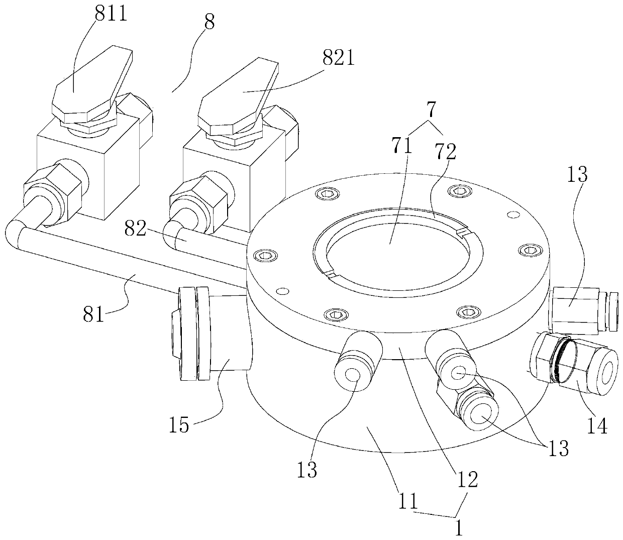
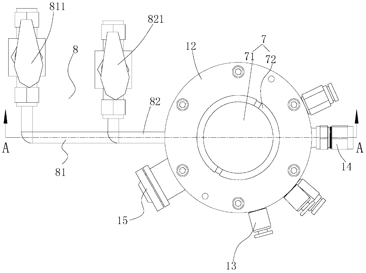
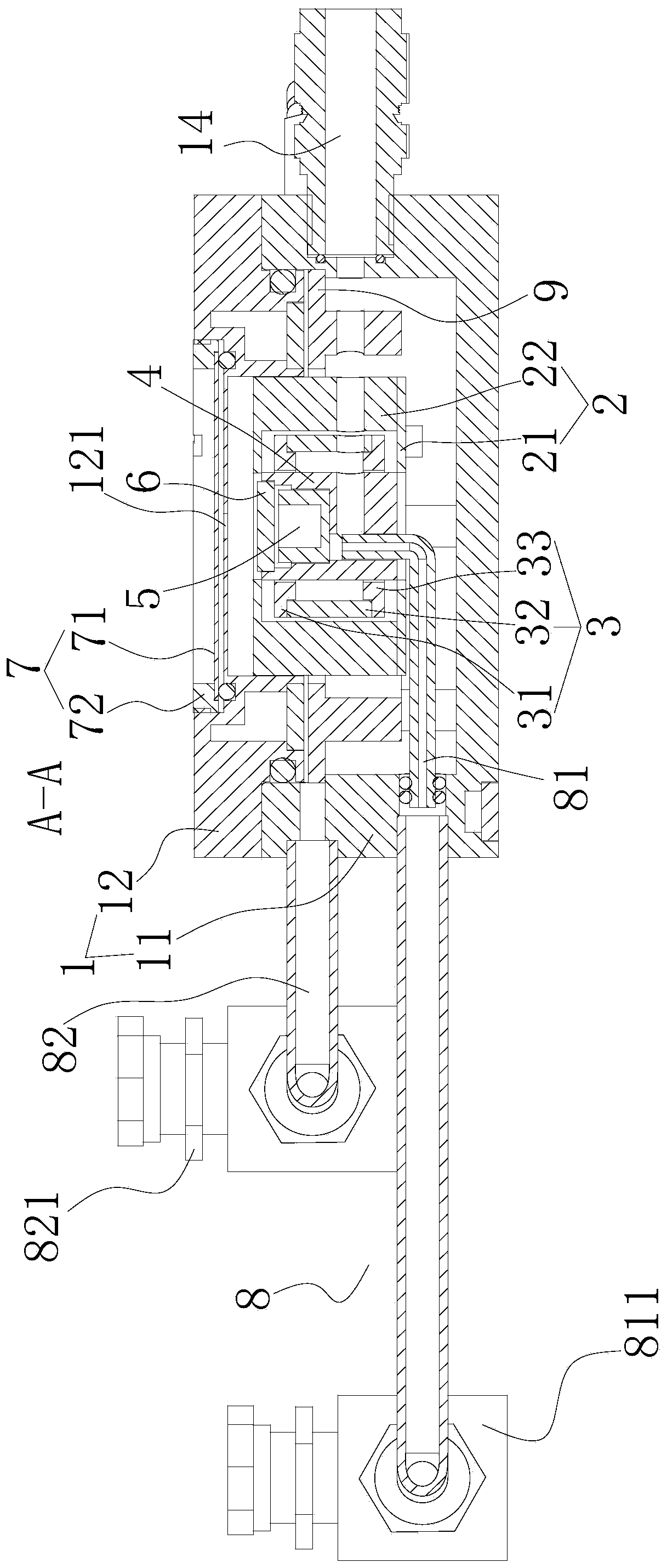
[0057] Such as Figure 1-3 As shown, an in-situ high-temperature spectroscopic testing device includes a housing 1 , a thermal insulation layer 2 , a heating furnace 3 , a sample stage 4 , a sample holder 5 , a sample cover 6 , a window 7 , and a gas system 8 .

[0058] Such as image 3 As shown, a heat insulation layer 2 is arranged in the shell 1, a heating furnace 3 is arranged in the heat insulation layer 2, a sample stage 4 is arranged in the heating furnace 3, a placement groove with an upward opening is provided in the sample stage 4, and a sample holder 5 is arranged in the placement groove, A sample cover 6 is arranged above the sample holder 5 , and a window 7 is arranged on the housing 1 above the sample cover 6 , and external light can pass through the window 7 and enter the sample holder 5 .

[0059] A cooling system is provided in the housing 1 , and a temperature detection device capable of detecting the temperature in the sample rack 5 is also included.

[00...

Embodiment 2

[0072] The difference between this embodiment and Embodiment 1 is:

[0073] Such as image 3 As shown, an annular heat insulation cover 9 is arranged between the lower shell 11 and the heat insulation layer 2, the heat insulation cover 9 is located at the bottom of the upper cover 12, and the bottom of the heat insulation cover 9 is installed on the bottom of the lower shell 9 through arc-shaped support blocks and screws. Shell 11.


PUM


Abstract

The invention relates to the field of in-situ characterization and particularly relates to an in-situ high-temperature spectrum testing device. The device comprises a shell; a heat insulation layer isarranged in the shell; a heating furnace is arranged in the heat insulation layer; a sample table is arranged in the heating furnace; a placement groove with an upward opening is formed in the sampletable; a sample holder is arranged in the placement groove; a sample cover is arranged above the sample holder; a window is formed in the shell above the sample cover; and external light can enter the sample holder through the window; a cooling system is arranged in the shell; the in-situ high-temperature spectrum testing device further comprises a temperature detection device which can be used for detecting the temperature in the sample holder; the device further comprises a gas path system; the interior and the exterior of the shell are sealed; and the gas path system can introduce gas fromthe lower portion of the sample holder, and the gas can be discharged out of the shell from the upper portion of the sample holder. With the in-situ high-temperature spectrum testing device of the invention adopted, various spectroscopy tests, gas environment and high pressure can be simultaneously considered.

Description

technical field [0001] The invention relates to the field of in-situ characterization, in particular to an in-situ high-temperature spectrum testing device. Background technique [0002] Solid oxide fuel cells (SOFCs) have attracted much attention due to their high conversion efficiency for converting various chemical fuels into electrical energy. However, performance degradation due to carbon deposition (coking) on ​​nickel-based anodes remains a technical challenge. At present, there are mainly two strategies to suppress the coking of nickel-based anodes. One is to add other gases such as steam, CO2 or O2 to hydrocarbon fuels. By adding these gases, the O / C ratio in the fuel increases, leading to a situation where carbon deposition can be thermodynamically avoided. However, adding other gases requires additional energy, reducing overall energy efficiency. The second strategy is to introduce an anode catalyst layer (e.g. RueCeO2 or Cu1.3Mn1.7O4) or to incorporate metals...

Claims


Application Information

Patent Timeline
IPC IPC(8): G01N21/35G01N21/65G01N21/25G01N21/01G01K7/02
CPCG01N21/35G01N21/65G01N21/25G01N21/01G01K7/02
Inventor 黄伟峰陈兴杨长春
Owner JIUJIANG UNIVERSITY
Why Eureka
Try Eureka