Urea solution continuous online batching system and solid feeding assembly thereof

A batching system and material feeding technology, which is applied in the direction of mixer accessories, dissolvers, mixers, etc., can solve the problems of high construction cost, limited layout location, and large volume of preparation equipment, so as to save equipment costs and reduce land occupation area effect

Pending Publication Date: 2020-07-31
上海鲁源控制设备有限公司
View PDF0 Cites 6 Cited by
  • Summary
  • Abstract
  • Description
  • Claims
  • Application Information

AI Technical Summary

Problems solved by technology

[0006] The above-mentioned batching process is carried out intermittently, each batching takes 3-6 hours, and the procedure is cumbersome. In order to meet the demand for ammonia in the flue gas denitrification system, the design of the dissolution tank is relatively large. Generally, one batching can meet the denitrification dosage of 20-24 hours. Therefore, the volume of the dissolution tank is large and the height is high. When feeding materials into the dissolution tank, a bucket elevator is required for feeding, and the bucket elevator is bulky and tall, so it is necessary to build a second floor or raise the overall roof height, and the layout position is limited
The preparation equipment of urea solution is bulky, occupies a large area, and the construction cost is high. The batching process takes a long time and the operation procedures are cumbersome, which has great limitations in use.

Method used


Image

  • Urea solution continuous online batching system and solid feeding assembly thereof
  • Urea solution continuous online batching system and solid feeding assembly thereof
  • Urea solution continuous online batching system and solid feeding assembly thereof

Examples


Embodiment 1

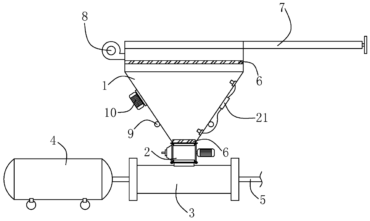
[0035] Such as figure 1 As shown, the present embodiment provides a solid feed assembly for continuous feeding, including a hopper 1 and a feed amount detector. The feed amount detector used in this embodiment is a level gauge 21, which is located in the hopper Two probes are set in 1, one is located at the upper position of hopper 1 to detect the upper limit of material feeding, and the other is located at the lower position of hopper 1 to detect the lower limit of material feeding. When the material in hopper 1 reaches the upper limit of feeding, stop feeding to prevent the material from overflowing from hopper 1; when the material in hopper 1 reaches the lower limit of feeding, stop the operation of rotary feeder 2 to ensure that the rotary feeder 2 The urea is of fixed capacity (not empty). There are two layers of filter screens 6 fixedly connected in the hopper 1, one layer is located near the top of the hopper 1, and the other side is located at the bottom of the hopper...

Embodiment 2

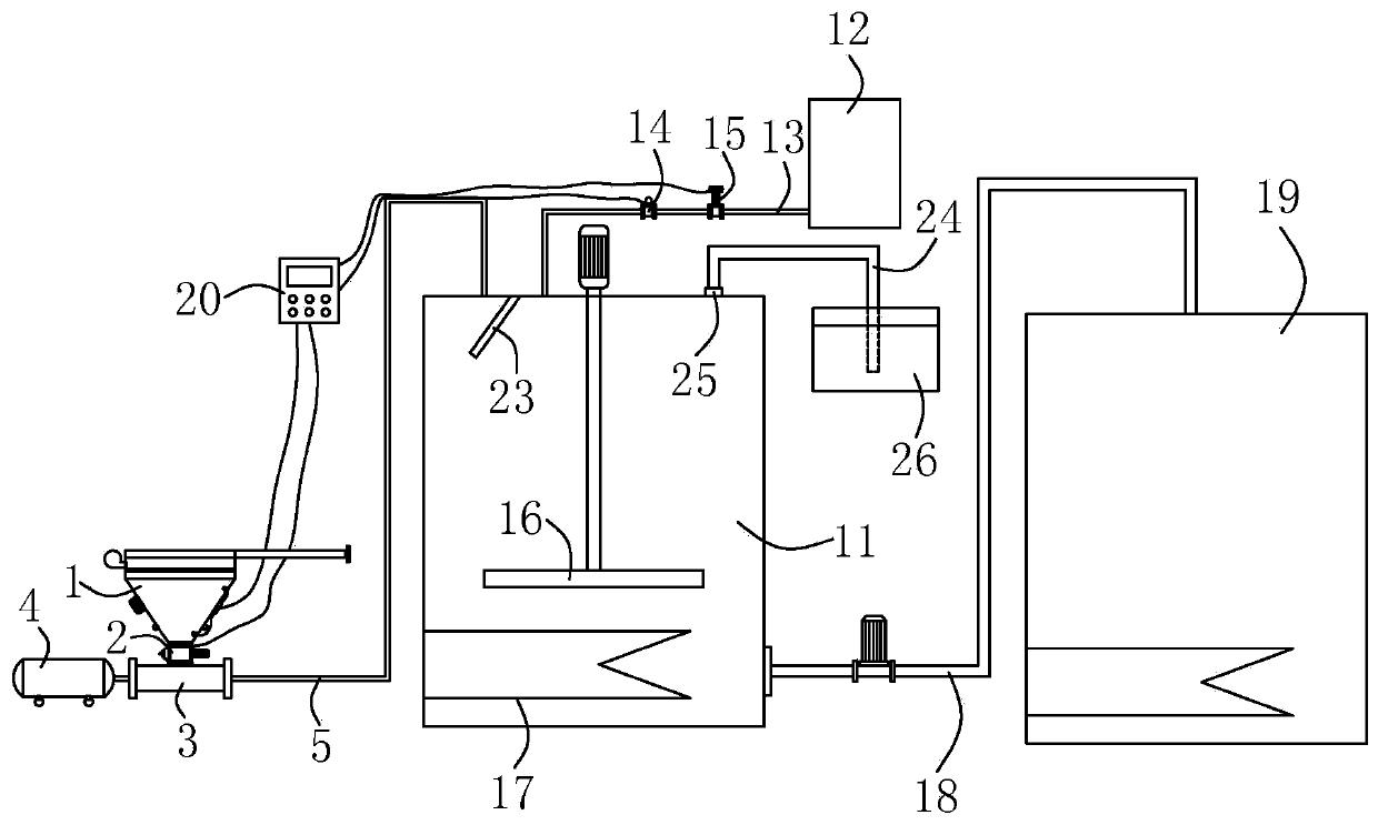
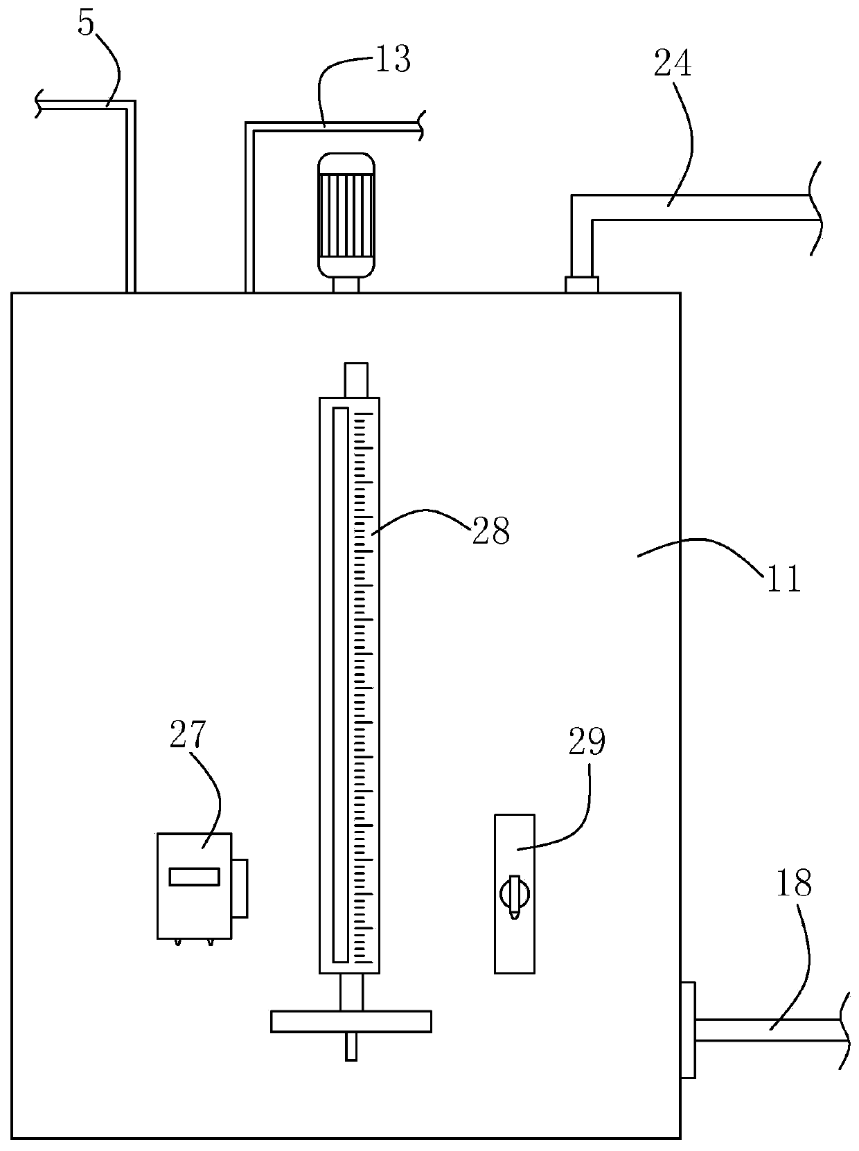
[0039] Such as figure 2 As shown, the present embodiment provides a continuous online batching system for urea solution, including a batching tank 11, the batching tank 11 is fixedly connected with the solid feed assembly of Embodiment 1, that is, one end of the feed pipe 5 and the gas-solid mixer 3 Fixedly connected, the other end is fixedly connected with the top of the batching tank 11, so that the material enters the batching tank 11 along the feed pipe 5 along with the airflow. A deflector 23 is fixedly connected to the position communicating with the feed pipe 5 in the batching tank 11. The deflector 23 used in this embodiment is a deflector, and the deflector is fixed to the connection of the feed pipe 5 in an oblique shape. place. In this way, when feeding, the airflow entraining urea particles impacts on the deflector, and the urea particles fall along the deflector into the batching tank 11, and the airflow moves upward under the obstruction of the deflector, which...

Embodiment 3

[0045] The difference between this embodiment and embodiment two mainly lies in: Figure 4 As shown, the feed amount detector of this embodiment adopts a solid flow meter 22, which is fixedly connected to the feed pipe 5, and the feed amount of urea particles is monitored by the solid flow meter 22. The solid flow meter 22, the water flow meter 14 and the regulating valve 15 are respectively electrically connected to the controller 20. When the feed amount transmitted by the solid flow meter 22 and the water flow meter 14 to the controller 20 does not meet the preset ratio, the controller 20 An instruction is sent to the regulating valve 15, and the regulating valve 15 is controlled to increase or decrease the water flow, so that the urea granules and water are fed synchronously according to the preset ratio. A reserved interface is provided on the feed pipe 5 between the solid flow meter 22 and the gas-solid mixer 3, and the reserved interface can be used to connect a tank tr...


PUM


Abstract

The invention discloses a urea solution continuous online batching system and a solid feeding assembly thereof, and belongs to the technical field of flue gas denitrification reducing agent systems. The solid feeding assembly comprises a hopper and a feeding amount detector, wherein the outlet side of the hopper is connected with a rotary feeder, and the side, away from the hopper, of the rotary feeder is fixedly connected with a gas-solid mixer. The invention further provides the urea solution continuous online batching system which comprises a batching tank, the solid feeding assembly is fixedly connected to the batching tank, and a liquid feeding assembly is further communicated to the batching tank. A stirring piece and a heating piece are arranged in the batching tank. Quantitative conveying and accurate metering can be conducted on solid materials, water is synchronously conveyed into the batching tank in proportion, continuous online batching of a urea solution can be achieved,immediate batching and immediate use are achieved, the device cost can be reduced, the batching efficiency can be improved, and the occupied area of the device can be reduced.

Description

technical field [0001] The invention relates to a continuous on-line batching system for urea solution and a solid feeding assembly thereof, belonging to the technical field of flue gas denitrification reducing agent systems. Background technique [0002] In the system for denitration treatment of flue gas, ammonia is a commonly used reducing agent, and has the highest removal efficiency for nitric oxide in flue gas. The ammonia used in the system is usually obtained from urea hydrolysis / pyrolysis, and the urea solution used in the urea hydrolysis / pyrolysis process is generally prepared from dry urea and water under the action of certain heat. The traditional batching method of urea solution mainly includes the following steps: [0003] Step 1: Add desalted water to the target water level in the dissolution tank, and heat the desalted water. The process of adding water and heating takes about 1-2 hours; [0004] Step 2: Elevate the dry urea with a bucket elevator and pour ...

Claims


Application Information

Patent Timeline
Patent Type & Authority Applications(China)
IPC IPC(8): B01F7/18B01F15/02B01F15/04B01F15/06B01F15/00
CPCB01F27/90B01F35/2132B01F35/2212B01F35/717B01F35/88B01F35/90B01F2035/99
Inventor 高良海
Owner 上海鲁源控制设备有限公司
Why Eureka
Try Eureka