Strip-type dielectric patch filtering antenna array

A technology for filtering antennas and media, which is applied in the direction of antenna arrays, antenna arrays that are energized separately, and antennas, etc., can solve the problems of unfavorable filtering antenna array structure simplification, lack of array filtering function fusion, and large media size, etc., to achieve size reduction and simplification structure, maintaining the effect of the half-wave distribution

Active Publication Date: 2020-07-31
NANTONG UNIVERSITY +1
View PDF6 Cites 6 Cited by
  • Summary
  • Abstract
  • Description
  • Claims
  • Application Information

AI Technical Summary

Problems solved by technology

At present, the dielectric filter antenna unit is mainly realized based on a dielectric resonator, so the dielectric size is large and the profile is high; while the dielectric filter antenna array is realized by forming an array through the dielectric filter antenna unit, and there is no fusion of the filtering function for the array itself, which is not conducive to filtering Simplified structure of the antenna array

Method used


Image

  • Strip-type dielectric patch filtering antenna array
  • Strip-type dielectric patch filtering antenna array
  • Strip-type dielectric patch filtering antenna array

Examples


Embodiment Construction

[0018] The present invention will be further explained below in conjunction with the accompanying drawings.

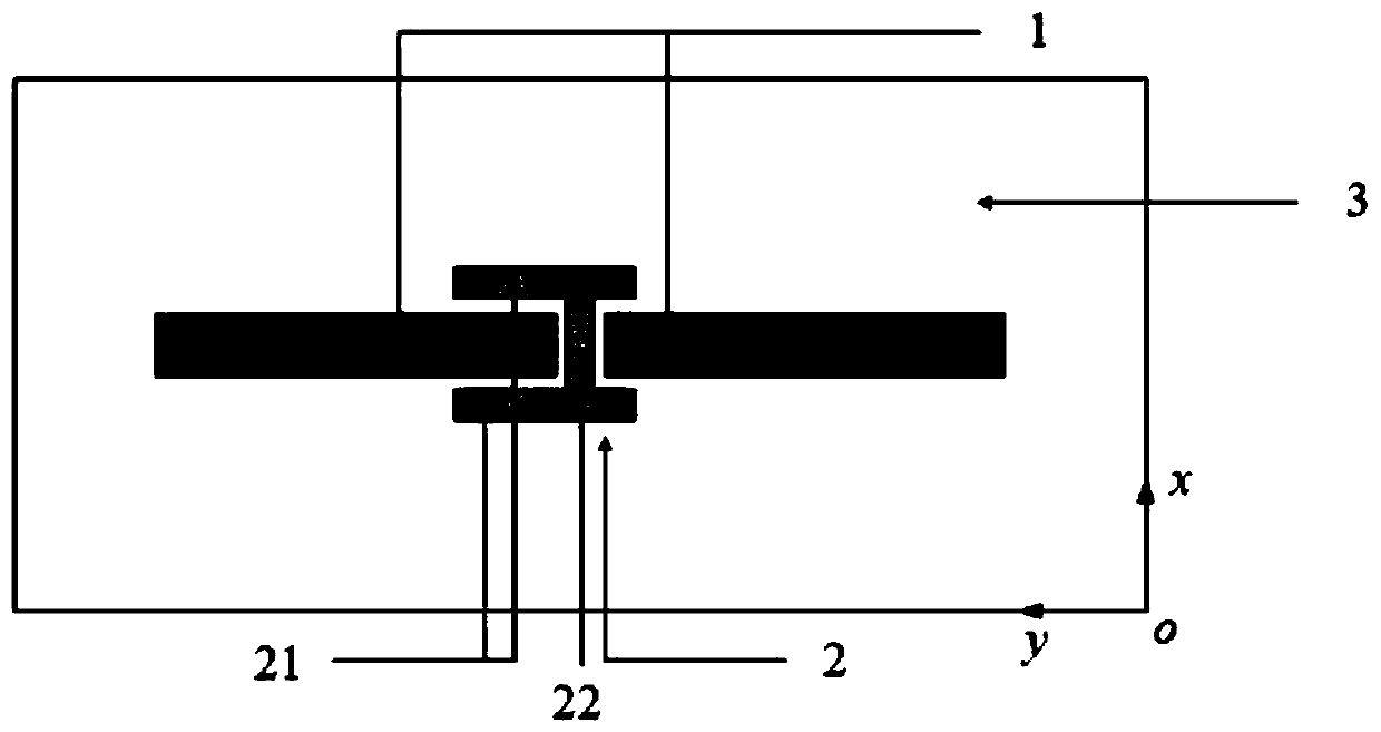
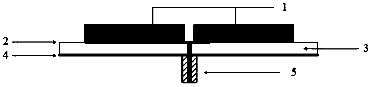
[0019] Such as figure 1 , figure 2 As shown, a strip dielectric patch filter antenna array includes two dielectric strips 1 , an H-shaped metal structure 2 , a dielectric substrate 3 , a metal ground 4 and a coaxial cable 5 . The H-shaped metal structure 2 is located on the upper surface of the dielectric substrate 3 , and the H-shaped metal structure 2 is composed of two metal strips 21 parallel to the y-axis and a metal strip 22 parallel to the x-axis. Two dielectric strips 1 are stacked above the dielectric substrate 3 , respectively located on both sides of the metal strip 22 on the x-axis and arranged parallel to the y-axis. The metal ground 4 is located on the lower surface of the dielectric substrate 3 , and the inner conductor of the coaxial line 5 penetrates from the bottom of the metal ground 4 and is connected to the center of the metal strip 22 .

[002...


PUM

PropertyMeasurementUnit
dielectric lossaaaaaaaaaa

Abstract

The invention discloses a strip-type dielectric patch filter antenna array which comprises an H-type microstrip line and 1 * 2 strip-type dielectric patch filter antenna arrays. The H-type microstripline is used as a microstrip feed structure of the 1 * 2 strip-type dielectric patch filter antenna arrays. After a signal is fed into the H-shaped microstrip line through a coaxial line, the microstrip lines formed by the two metal strips parallel to the y axis in the H-shaped microstrip line are in half-wave distribution. Two strip-type dielectric patch antenna units working in the TM delta 1 mode are jointly coupled to symmetrical microstrip lines distributed in a half-wave mode, and 1 * 2 strip-type dielectric patch filter antenna arrays and the working frequency band thereof are formed. Use of a traditional power distribution network is avoided, and a TM delta 2 mode of the strip-type dielectric patch antenna units are utilized to form a high-end radiation zero point to improve frequency selectivity, so that reduction of the size and loss of the filtering antenna array, reduction of the profile and simplification of the structure are facilitated.

Description

technical field [0001] The invention relates to the field of microwave communication, in particular to a strip type dielectric patch filter antenna array. Background technique [0002] Modern wireless communication systems are developing toward high integration, low power consumption, and miniaturization; the filter antenna has both filtering and radiation functions, which reduces the number of components, improves system integration, and reduces system loss and size. s concern. According to the type of radiator material, filter antennas can be divided into metal filter antennas and dielectric filter antennas. Compared with the metal filter antenna, the dielectric filter antenna has the advantages of low conductor loss and high degree of adjustment freedom, and is quite different from the metal filter antenna in the antenna working mode. [0003] Dielectric filter antennas are divided into dielectric filter antenna units and dielectric filter antenna arrays according to th...

Claims


Application Information

Patent Timeline
Patent Type & Authority Applications(China)
IPC IPC(8): H01Q1/36H01Q1/38H01Q1/48H01Q1/50H01Q21/06
CPCH01Q1/48H01Q1/36H01Q1/38H01Q1/50H01Q21/065
Inventor 施金刘栩徐凯
Owner NANTONG UNIVERSITY
Why Eureka
Try Eureka