Stent replacement system suitable for urinary retention and urinary incontinence
A stent system and urinary incontinence technology, applied in the field of medical devices, can solve the problems of inability to effectively support the urethra of the prostate, lack of intelligent control means, cross-infection, etc. The effect of ensuring stability
- Summary
- Abstract
- Description
- Claims
- Application Information
AI Technical Summary
Problems solved by technology
Method used
Image
Examples
Embodiment 1
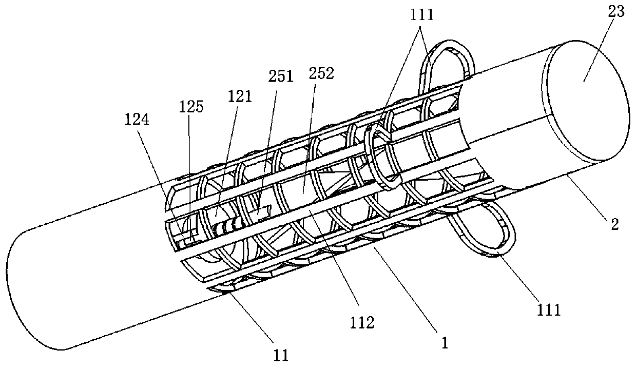
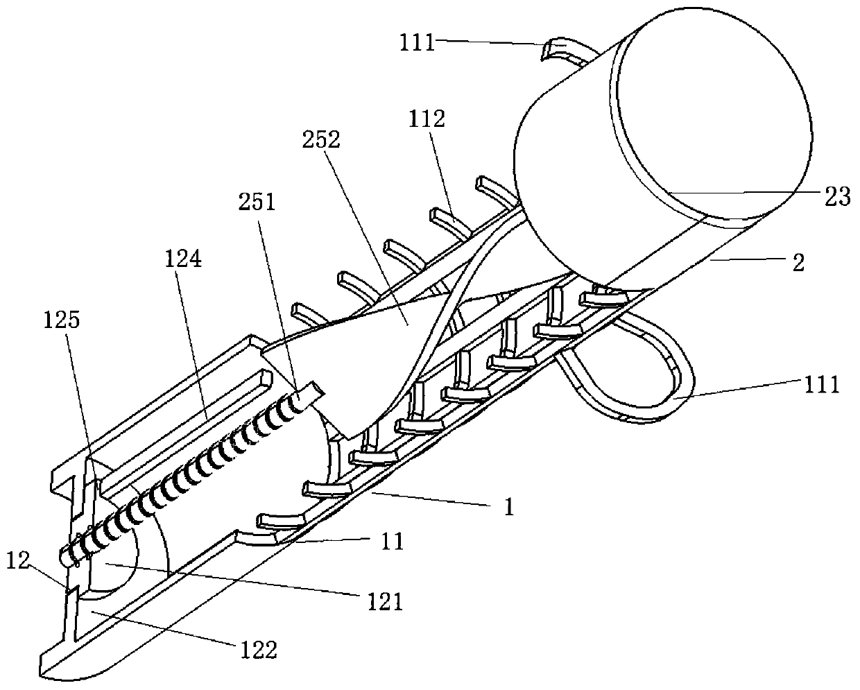
[0042] Please see attached figure 1 , attached figure 2 , with figure 1 It is a three-dimensional schematic diagram of a bracket replacement system suitable for urinary retention and urinary incontinence of the present invention; figure 2 It is a partial sectional view of a stent replacement system suitable for urinary retention and urinary incontinence of the present invention.
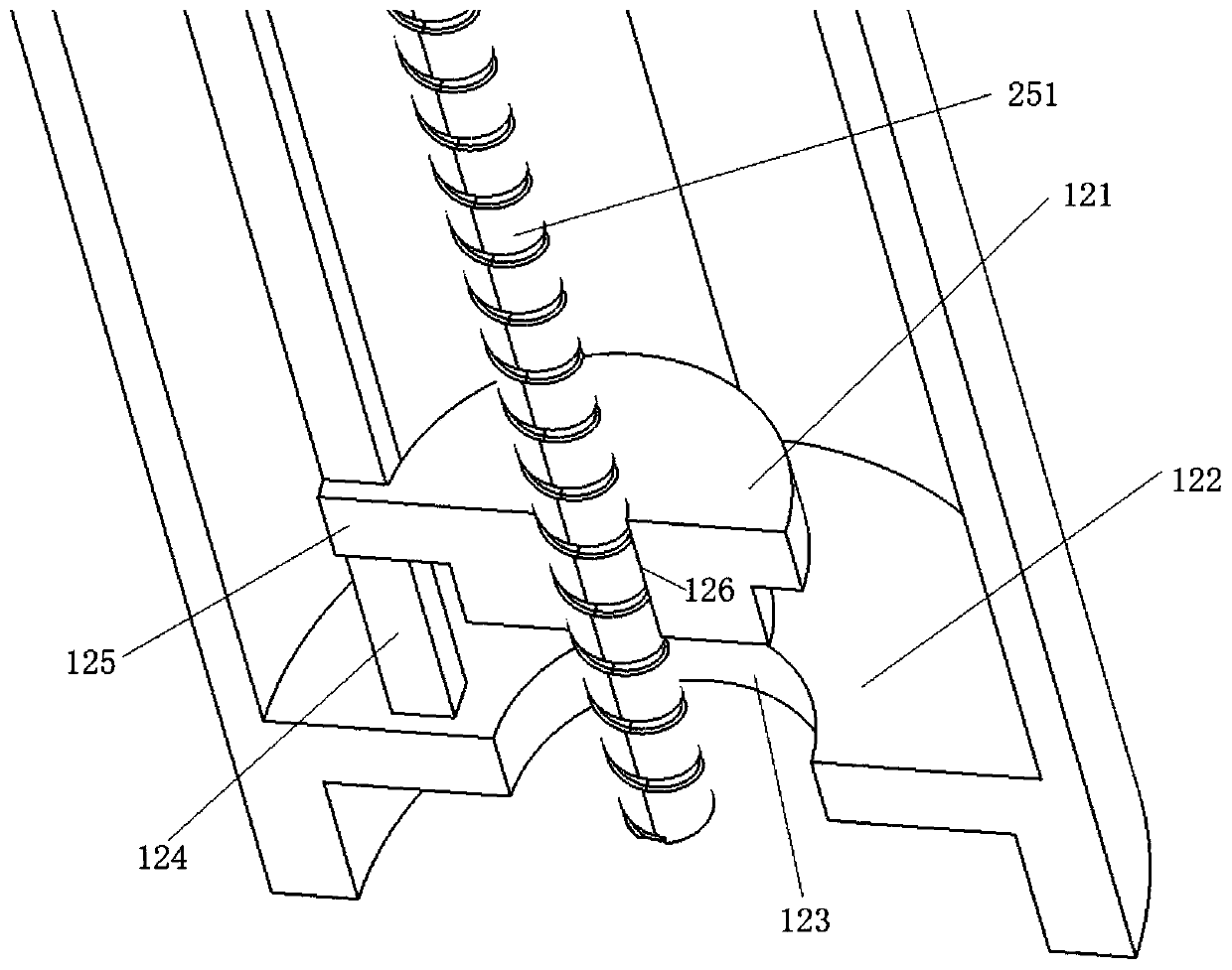
[0043] A stent replacement system suitable for urinary retention and urinary incontinence, comprising a stent system 1 and a control system 2; the stent system 1 is connected to the control system 2; the stent system 1 includes a urethral stent 11 and a valve 12;
[0044] The urethral stent 11 is a cylindrical tubular channel, including several anti-falling ears 111 and expansion nets 112, and its surface is covered with an antibacterial coating, such as Agion antibacterial material, which can reduce the risk of urinary tract infection caused by long-term indwelling catheters;
[0045] The anti-of...
Embodiment 2
[0054] Please see attached Figure 5 ; attached Figure 5 It is a partial sectional view of the valve of another stent replacement system suitable for urinary retention and urinary incontinence of the present invention. This embodiment is basically the same as Embodiment 1, the difference is that pressure sensing sheets 127 are provided on both side walls of the gear rod 124, and the pressure sensing sheets 127 are electrically connected to the central control module 22, It should be noted that, during the opening and closing process of the valve 12, the gear rod 124 is in contact with the blocking plate 125, and the pressure sensing piece 127 can detect the contact between the gear rod 124 and the blocking plate. The pressure change signal between 125 is fed back to the central control module 22, and then transmitted to the external display device terminal 26 by the signal transmission module 24. When the pressure value reaches a certain limit, a safety warning can be issued...
PUM
 Abstract
Description
Claims
Application Information
 - R&D
- Intellectual Property
- Life Sciences
- Materials
- Tech Scout
- Unparalleled Data Quality
- Higher Quality Content
- 60% Fewer Hallucinations
Browse by: Latest US Patents, China's latest patents, Technical Efficacy Thesaurus, Application Domain, Technology Topic, Popular Technical Reports.
© 2025 PatSnap. All rights reserved.Legal|Privacy policy|Modern Slavery Act Transparency Statement|Sitemap|About US| Contact US: help@patsnap.com


