Intelligent traffic positioning recognition system and method

A positioning recognition and intelligent traffic technology, applied in the field of intelligent traffic positioning and recognition systems, can solve problems such as traffic congestion, traffic accidents, inability to obtain traffic lights accurately and in time, achieve high availability, low cost, and avoid traffic chaos and congestion Effect

Inactive Publication Date: 2020-08-04
中铁检验认证中心有限公司 +2
View PDF6 Cites 2 Cited by
  • Summary
  • Abstract
  • Description
  • Claims
  • Application Information

AI Technical Summary

Problems solved by technology

However, in case of severe weather such as heavy rain, heavy snow, dense fog, or special terrain, the camera cannot accurately and timely obtain the status of traffic lights, which may easily cause traffic jams and even cause traffic accidents

Method used


Image

  • Intelligent traffic positioning recognition system and method
  • Intelligent traffic positioning recognition system and method
  • Intelligent traffic positioning recognition system and method

Examples


Embodiment 1

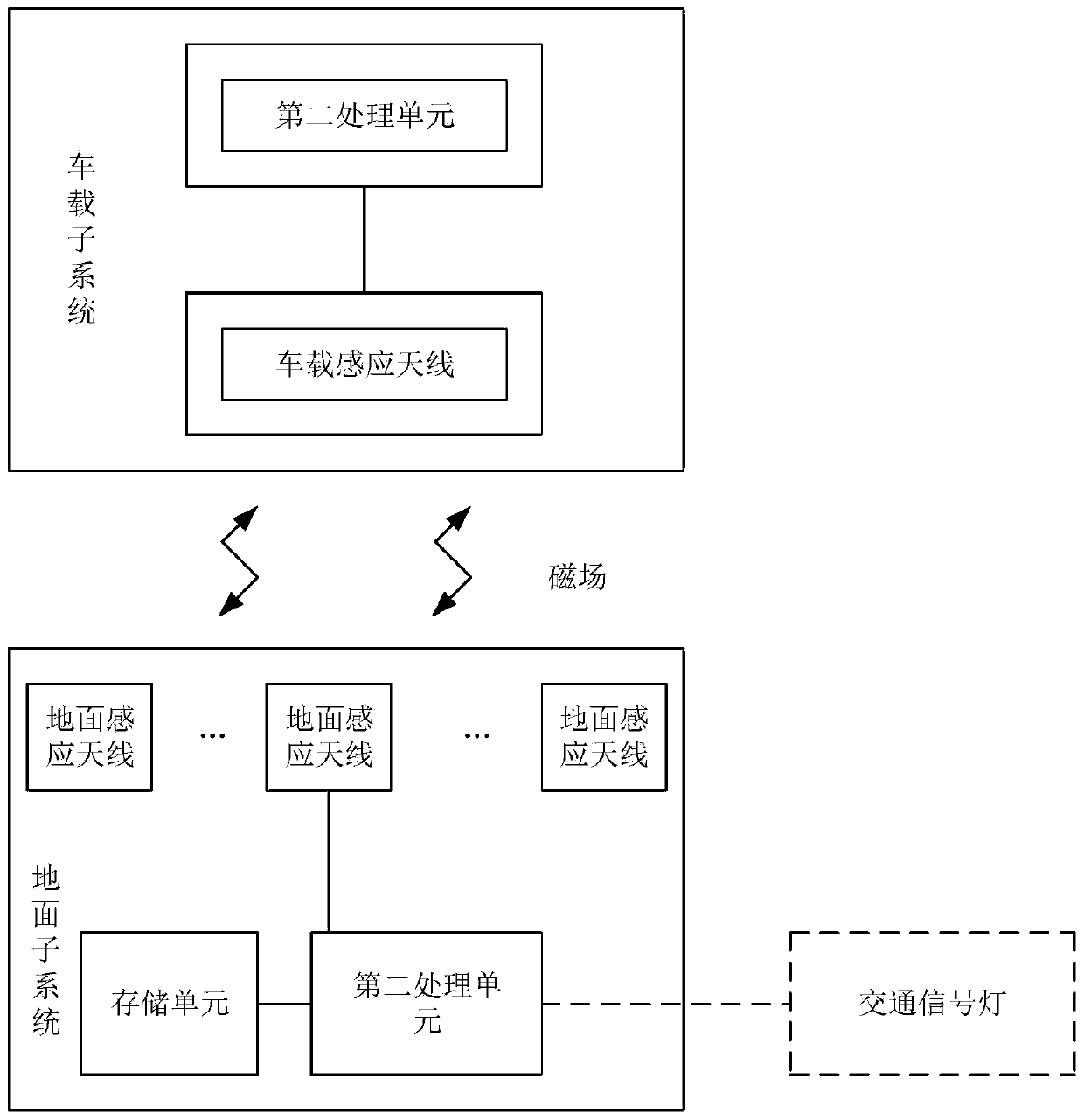
[0038] figure 1 It is a schematic structural diagram of an intelligent traffic positioning and identification system provided by an embodiment of the present invention, see figure 1 , the positioning recognition system includes a ground subsystem and a vehicle subsystem, wherein,

[0039] The ground subsystem includes a ground induction antenna, a storage unit, and a first processing unit; the first processing unit is used to receive the status of a signal light, and the storage unit stores coordinate information of the ground induction antenna and vehicle speed limit information; the The first processing unit sends the status of the traffic signal light, the coordinate information of the ground sensing antenna and the vehicle speed limit information to the ground sensing antenna; the ground sensing antenna converts the status of the traffic signal light, the coordinate information of the ground sensing antenna and the vehicle speed limit information is magnetic field informa...

Embodiment 2

[0060] Figure 4 It is a schematic flow chart of an intelligent traffic location recognition method provided by an embodiment of the present invention, see Figure 4 , the method includes the following steps:

[0061] Obtain the status of traffic lights, coordinate information of ground sensing antennas and vehicle speed limit information;

[0062] Converting the status of the traffic signal light, the coordinate information of the ground induction antenna and the vehicle speed limit information into magnetic field information;

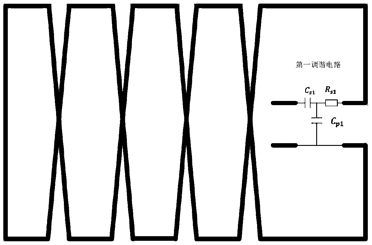
[0063] Based on the magnetic field information, an induced voltage signal is generated by electromagnetic induction; specifically, when the induced voltage signal passes through the continuous 8-shaped intersection of the ground induction antenna, the phase of the magnetic field of the magnetic field information received by the ground induction antenna changes, thereby affecting all The on-board subsystem is used for positioning;

[0064] Demodulat...


PUM


Abstract

The invention discloses an intelligent traffic positioning recognition system and method. The system comprises a ground subsystem and a vehicle-mounted subsystem. The ground subsystem comprises a ground induction antenna, a storage unit and a first processing unit; the ground induction antenna converts the traffic signal lamp state, the coordinate information of the ground induction antenna and the vehicle speed limit information into magnetic field information, generates an induction voltage signal from the magnetic field information through electromagnetic induction, and sends the inductionvoltage signal to the vehicle-mounted subsystem; the vehicle-mounted subsystem comprises a vehicle-mounted induction antenna and a second processing unit; and the vehicle-mounted induction antenna sends the induction voltage signal to a second processing unit, and the second processing unit demodulates the induction voltage signal to obtain the state of the traffic signal lamp, the coordinate information of the ground induction antenna and the speed limiting information. High-precision positioning information is automatically received, the state of the traffic signal lamp is recognized, and speed limiting information of the current road section can be received; and the system is not influenced by severe weather and special terrains and has high anti-interference capability.

Description

technical field [0001] The invention belongs to the technical field of intelligent traffic positioning, in particular to an intelligent traffic positioning recognition system and method. Background technique [0002] With the rapid development of artificial intelligence, autonomous driving technology has become a research hotspot. In the United States, self-driving cars have moved from the lab to public roads. In China, self-driving cars are in the research and testing stage, and some cities have specially designated road sections for self-driving car tests. [0003] One of the key technologies of autonomous driving is positioning. The on-board computer needs to determine the safe driving speed at the current location based on the positioning. At present, most of the positioning information required for automatic driving comes from satellite navigation and positioning systems. Due to factors such as orbit error, clock error, ionospheric delay, tropospheric delay, multipat...

Claims


Application Information

Patent Timeline
Patent Type & Authority Applications(China)
IPC IPC(8): G01C21/28
CPCG01C21/28
Inventor 朱林富李鹍许波李鑫李洋李小帅李博马研姚珍富张强
Owner 中铁检验认证中心有限公司
Why Eureka
Try Eureka