Optical curve grinding wheel and preparing method thereof

An optical curve grinding and grinding wheel technology, which is used in grinding/polishing equipment, abrasives, grinding devices, etc., can solve the problems of inability to carry out mass production of chamfered grinding wheels, inability to process chamfered grinding wheels, and changes in grinding performance. It is not easy to lose accuracy, facilitates heat transfer, and reduces the effect of grinding temperature

Active Publication Date: 2020-08-07
ZHENGZHOU RES INST FOR ABRASIVES & GRINDING CO LTD
View PDF8 Cites 1 Cited by
  • Summary
  • Abstract
  • Description
  • Claims
  • Application Information

AI Technical Summary

Problems solved by technology

[0003] At present, there are mainly three ways of dressing the chamfering grinding wheel of this kind of metal bond superhard material, which are electrolytic grinding dressing, spark machine online dressing, and mechanical dressing. The device is on-line dressing, and the accuracy is seriously lost after disassembly, so it is impossible to carry out mass production of chamfering grinding wheels; spark machine dressing is currently the main dressing method for metal bond superhard material grinding wheels, but because spark machine dressing is a large current discharge in a short period of time, It is easy to cause the segregation of low melting point metal elements to change the bond composition of the repaired grinding wheel. The change of the composition will lead to the change of the grinding performance of the repaired grinding wheel, and the problem of unstable performance will easily occur when processing the workpiece; the above problems do not exist in mechanical dressing. However, no matter whethe

Method used


Image

  • Optical curve grinding wheel and preparing method thereof
  • Optical curve grinding wheel and preparing method thereof
  • Optical curve grinding wheel and preparing method thereof

Examples


Embodiment 1

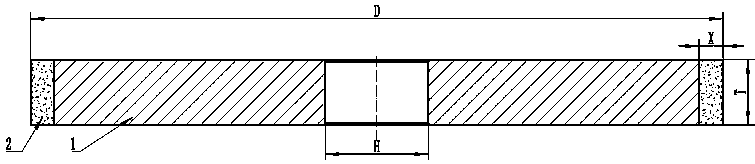
[0033] Such as image 3 As shown, an optical curve grinding wheel includes a stainless steel substrate 1 and an abrasive layer 2, wherein the abrasive layer 2 includes abrasive materials and a metal bond, and is specifically composed of the following raw materials in parts by weight: 35 parts of copper powder, tin powder 25 parts, silver powder 10 parts, cubic boron nitride 30 parts (400 mesh).

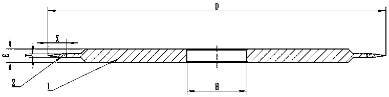
[0034] The thickness of the abrasive layer 2 is lower than that of the substrate 1, and the edge of the abrasive layer 2 is designed with sharp corners, which is more convenient for dressing the chamfering grinding wheel. In the present invention, the emery wheel model that adopts is 14E1 , where: D represents the diameter of the grinding wheel, T represents the thickness of the abrasive layer, H represents the diameter of the inner hole of the grinding wheel, E represents the total thickness of the grinding wheel substrate, and X represents the width of the abrasive layer.

[0035...

Embodiment 2

[0044] For the optical curve grinding wheel provided in this embodiment, compared with Embodiment 1, the formulation of the abrasive layer is adjusted as follows:

[0045] The abrasive layer is composed of the following raw materials in parts by weight: 30 parts of copper, 25 parts of tin, 5 parts of silver powder, and 40 parts of cubic boron nitride; the mesh size of the cubic boron nitride is 280 mesh.

[0046]Compared with the preparation method of the optical curve grinding wheel in Example 1, adjust some preparation parameters as follows:

[0047] Step 1) Take 5 parts of copper powder, 5 parts of silver powder, 40 parts of abrasive, and the mixing time of the abrasive layer in the three-dimensional mixer is 20 hours;

[0048] Step 4) In a heat-resistant steel mold at 2500kg / cm 2 pressure to suppress;

[0049] Step 5) In a double-body hot-pressing sintering furnace, the temperature is raised to 500° C. at a rate of 100° C. / h and kept for 2 hours for molding and sintering...

Embodiment 3

[0051] For the optical curve grinding wheel provided in this embodiment, compared with Embodiment 1, the formulation of the abrasive layer is adjusted as follows:

[0052] The abrasive layer is made of the following raw materials in parts by weight: 33 parts of copper, 26 parts of tin, 6 parts of silver powder, and 35 parts of cubic boron nitride; the mesh size of the cubic boron nitride is 400 mesh.

[0053] Compared with the preparation method of the optical curve grinding wheel in Example 1, adjust some preparation parameters as follows:

[0054] Step 1) Take 3 parts of copper powder, 6 parts of silver powder, 35 parts of abrasive, and the mixing time of the abrasive layer in the three-dimensional mixer is 10 hours;

[0055] Step 4) In a heat-resistant steel mold at 2000kg / cm 2 pressure to suppress;

[0056] Step 5) Raise the temperature to 450° C. at a rate of 100° C. / h in a double-body hot-pressing sintering furnace and keep it for 1.5 hours.


PUM

PropertyMeasurementUnit
Meshaaaaaaaaaa
Meshaaaaaaaaaa

Abstract

The invention belongs to the technical field of ultra-hard grinding wheel dressing, and particularly relates to an optical curve grinding wheel for metal bonding agent ultra-hard material chamfering grinding wheel dressing. The optical curve grinding wheel comprises a base body and a grinding material layer. The grinding material layer comprises following raw materials including, by weight, 30-40parts of grinding materials and 60-70 parts of a metal bonding agent. The metal bonding agent comprises following raw materials including, by weight, 30-55 parts of copper powder, 25-50 parts of tin powder and 5-10 parts of silver powder. The grinding wheel is simple in formula and machining technology and simple and convenient to operate. Dressing can be conducted on a metal bonding agent ultra-hard material chamfering grinding wheel, the machining effect is good, the size of a chamfering grinding wheel tiny groove can reach the precision of +/- 0.01 mm.

Description

technical field [0001] The invention belongs to the technical field of dressing superhard grinding wheels, and in particular relates to an optical curve grinding wheel used for dressing chamfering grinding wheels of metal bond superhard materials and a preparation method thereof. Background technique [0002] Metal bond superhard material chamfering grinding wheel is mainly used for processing the edges and corners of metal, ceramics, glass and other materials. There are concentric arc micro-grooves distributed on the outer circle. schematic diagram see figure 1 with figure 2 ). [0003] At present, there are mainly three ways of dressing the chamfering grinding wheel of this kind of metal bond superhard material, which are electrolytic grinding dressing, spark machine online dressing, and mechanical dressing. The device is on-line dressing, and the accuracy is seriously lost after disassembly, so it is impossible to carry out mass production of chamfering grinding wheel...

Claims


Application Information

Patent Timeline
IPC IPC(8): B24D3/06B24D3/10B24D3/34B24D18/00C22C32/00C22C30/04C22C30/02C22C1/05C22C1/10B22F1/00B22F3/02B22F3/10B22F5/00
CPCB24D3/06B24D3/10B24D3/342B24D18/0009C22C26/00C22C32/0068C22C30/04C22C30/02C22C1/051B22F3/02B22F3/1007B22F5/00C22C2026/003B22F2005/001B22F2999/00B22F1/052B22F2201/013
Inventor 李国伟张毅牛俊凯于鸿飞
Owner ZHENGZHOU RES INST FOR ABRASIVES & GRINDING CO LTD
Why Eureka
Try Eureka