Dual-motor driving device of electric automobile

A dual-motor drive, electric vehicle technology, applied to electric vehicles, electromechanical devices, power devices, etc., can solve problems such as insufficient power and large power consumption

Pending Publication Date: 2020-08-07
山东宏泰机械科技股份有限公司
View PDF0 Cites 2 Cited by
  • Summary
  • Abstract
  • Description
  • Claims
  • Application Information

AI Technical Summary

Problems solved by technology

[0007] The purpose of the present invention is to provide a dual-motor drive device for electric vehicles, which aims to solve the problems of insufficient power and high power consumption during high-speed driving of existing electric vehicles during the starting stage and low-speed climbing stage

Method used


Image

  • Dual-motor driving device of electric automobile
  • Dual-motor driving device of electric automobile
  • Dual-motor driving device of electric automobile

Examples


no. 1 example

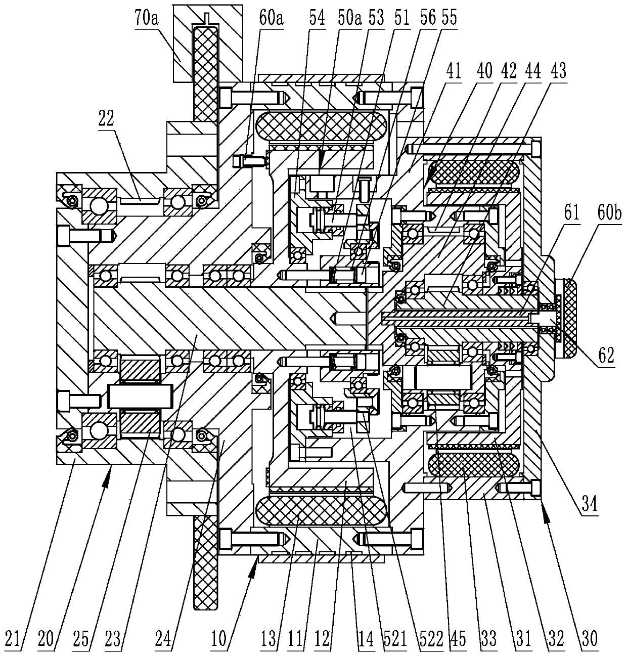
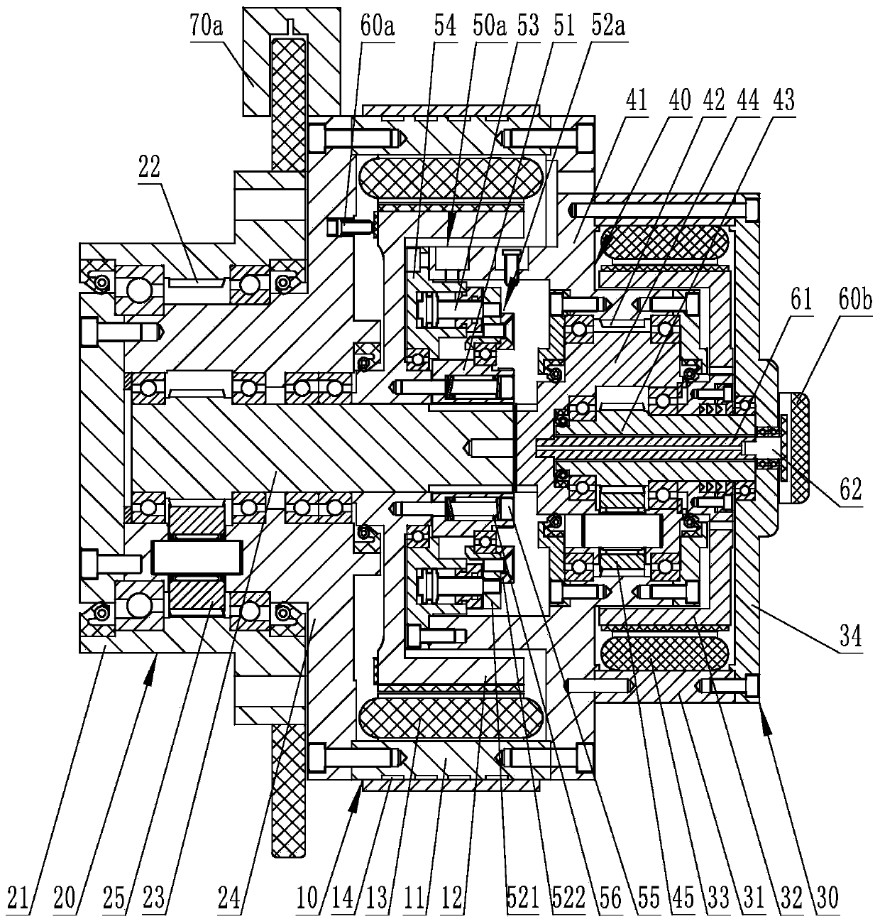
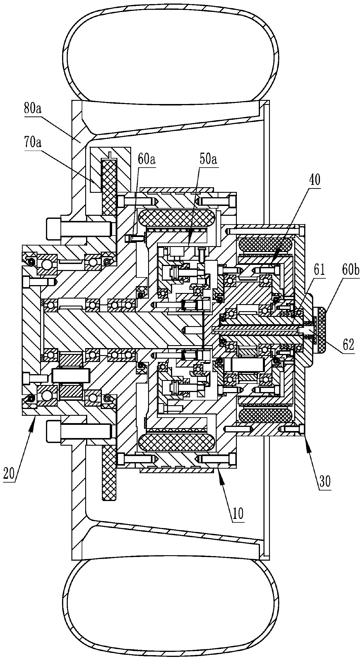
[0036] Depend on figure 1 , figure 2 and image 3 It can be seen that the dual-motor driving device for electric vehicles includes a first inner rotor motor 10, a first planetary reduction mechanism 20 arranged at one end of the first inner rotor motor 10, a second inner rotor mechanism 20 arranged at the other end of the first inner rotor motor 10, The rotor motor 30, and the second planetary reduction mechanism 40 arranged between the second inner rotor motor 30 and the first inner rotor motor 10;

[0037] The first inner rotor motor 10 includes a first stator 11, a first rotor 12 set together with the first stator 11, and a first coil magnet winding arranged between the first stator 11 and the first rotor 12. 13;

[0038] The first planetary reduction mechanism 20 includes a first sun gear shaft 23, a first sun gear arranged on the first sun gear shaft 23, and a first planetary gear fixedly connected to the first stator 11 and rotatably mounted on the first sun gear sha...

no. 2 example

[0052] Depend on Figure 4 It can be seen that this embodiment is basically the same as the first embodiment, the differences are:

[0053] The clutch mechanism is a hydraulic clutch 50c, the connection plate 52b of the hydraulic clutch 50c is an integral structure, and is installed together with the inner gear sleeve 51 through bearings, and the hydraulic clutch 50c is used to drive the connection plate 52b and the inner gear sleeve 51 to perform axial rotation. A plurality of moving oil cylinders 53 are arranged between the connecting plate 52b and the second housing 41. Usually, a second housing installation hole is respectively provided on the second housing 41 corresponding to each oil cylinder 53, and the corresponding oil cylinders 53 are fixed on the second housing. Two shell installation holes.

no. 3 example

[0055] Depend on Figure 5 and Figure 6 It can be seen that this embodiment is basically the same as the first embodiment, the differences are:

[0056] The clutch mechanism is an electromagnetic clutch 90. The electromagnetic clutch 90 includes a clutch housing 91, a driven plate 92, and a driving plate 93. The driving plate 93 is fixedly connected to the first sun gear shaft 23, and the driven plate 92 is connected to the second planetary wheel carrier 44. Fixedly connected, the driving plate 93 and the driven plate 92 are relatively rotatable anti-torque connections, and a slip ring 94 is provided on the second housing 41 to supply power to the coil of the electromagnetic clutch 90. The structure and principle of the electromagnetic clutch are those of ordinary skill in the art. Well-known, do not repeat them here.

[0057] During work, the rotation parameter of the first sun gear shaft 23 (referred to as the rotational speed of the first sun gear shaft 23 in this embodi...


PUM


Abstract

The invention belongs to the technical field of electric vehicles, especially relating to a double-motor driving device of an electric automobile which comprises a first planetary speed reducing mechanism, a first inner rotor motor, a second planetary speed reducing mechanism and a second inner rotor motor which are arranged in sequence. A first rotor is fixed to a first sun wheel shaft. A first planet carrier or a first shell is fixedly connected with a first stator. A second shell is fixedly connected with the first stator, the second stator is fixedly connected with the second shell and thefirst stator, and the second rotor is fixed to the second sun wheel shaft. The clutch mechanism is arranged between the first sun gear shaft and the second planet carrier, the first detection feedback structure is arranged corresponding to the first sun gear shaft, and the second detection feedback structure is arranged corresponding to the second planet carrier. Synchronous connection between afirst planet speed reducing mechanism and a second planet speed reducing mechanism can be achieved, running is stable, the blocking phenomenon is avoided, and the problems that power is insufficient during starting and low-speed climbing, and power consumption is large during high-speed running are solved.

Description

technical field [0001] The invention belongs to the technical field of electric vehicles, and in particular relates to a dual-motor drive device for electric vehicles. Background technique [0002] The hub motor, also known as the built-in wheel motor, is a technology that places the electric motor used to drive the electric vehicle inside the rim and outside the hub. Its biggest feature is the integration of power, transmission and braking devices into the hub. Therefore, The mechanical part of the electric vehicle is greatly simplified. [0003] The hub motor drive system is mainly divided into two structural types according to the rotor type of the motor, one is the inner rotor type, and the other is the outer rotor type. [0004] The outer rotor type adopts a low-speed outer rotor motor. The maximum speed of the motor is 1000-1500r / min. There is no deceleration device. The speed of the wheel is the same as that of the motor. Since a large torque is required for low-spee...

Claims


Application Information

Patent Timeline
Patent Type & Authority Applications(China)
IPC IPC(8): B60K7/00B60K17/04B60K17/02H02K7/116H02K7/10H02K7/114
CPCB60K7/0007B60K17/02B60K17/046B60K2007/0038B60K2007/0092H02K7/10H02K7/114H02K7/116Y02T10/64
Inventor 杜明乾
Owner 山东宏泰机械科技股份有限公司
Why Eureka
Try Eureka