
A Vertical Flow Constructed Wetland Structure and Configuration Method for Improving Electric Energy Capture During Sewage Purification

A technology for artificial wetland and sewage purification, applied in chemical instruments and methods, biological water/sewage treatment, water/sludge/sewage treatment, etc., can solve the problems of non-conductive filler matrix without breakthrough, decreased Coulombic efficiency, and increased internal resistance and other issues to achieve the effect of improving the electron capture ability

Active Publication Date: 2021-09-24
INST OF AQUATIC LIFE ACAD SINICA
View PDF6 Cites 0 Cited by
  • Summary
  • Abstract
  • Description
  • Claims
  • Application Information

AI Technical Summary

Problems solved by technology

[0003] However, with the scale-up of the constructed wetland-microbial fuel cell coupling system (CW-MFC), elements such as the substrate, plant roots, and electrode materials in the system will cause an increase in internal resistance, resulting in a decrease in Coulombic efficiency and a decrease in output power density.
At present, the plants used in the vertical flow constructed wetland-microbial fuel cell (VFCW-MFC) coupling system are generally conventional species that are well screened for microcurrent adaptation to the environment, and the selection of non-conductive filler substrates has not broken through conventional constructed wetland substrate materials (ZL 201310454037.7)

Method used


Image

  • A Vertical Flow Constructed Wetland Structure and Configuration Method for Improving Electric Energy Capture During Sewage Purification
  • A Vertical Flow Constructed Wetland Structure and Configuration Method for Improving Electric Energy Capture During Sewage Purification
  • A Vertical Flow Constructed Wetland Structure and Configuration Method for Improving Electric Energy Capture During Sewage Purification

Examples


Embodiment 1

[0036]A method for improving the vertical flow constructed wetland configuration of electric energy capture in the sewage purification process, the steps are as follows:

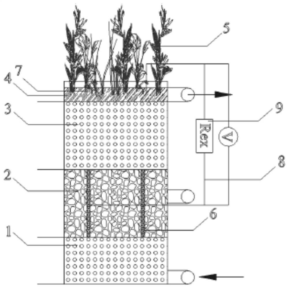
[0037] A. Sewage enters continuously from the bottom of the system and distributes water evenly, and then rises in push flow along the non-conductive filler layer 1 at the bottom. Under the adsorption, retention and oxidation of fillers and microorganisms in this layer, most of the oxygen in the sewage is consumed;

[0038] B. The sewage after step A flows into the anode conductive filler layer 2, the growth and enrichment of the electrogenic bacteria group is promoted in an anaerobic environment and electrons are generated, and the electrons flow out through the anode collector through the outer wire 8, and pass through the outer wire 8 and the load 9 Then flow into the cathode collector 7;

[0039] C, then the sewage flows into the non-conductive filler isolation layer 3, the main function of the non-condu...

Embodiment 2

[0047] A vertical flow artificial wetland structure that improves electrical energy capture in the process of sewage purification. This configuration is laid from bottom to top with a bottom non-conductive filler layer 1, an anode conductive filler layer 2; a non-conductive filler isolation layer 3; a cathode conductive filler layer 4; It is characterized in that: the anode conductive filler layer 2 is connected to the bottom non-conductive filler layer 1 and the non-conductive filler isolation layer 3 respectively, the cathode conductive filler layer 4 is connected to the non-conductive filler isolation layer 3, and in the non-conductive filler isolation layer 3 Wetland plants 5 are planted, the anode collector 6 and the cathode collector 7 are connected by an outer wire 8, the anode collector 6 and the cathode collector 7 are respectively placed in the anode conductive filler layer 2 and the cathode conductive filler layer 4, and the anode collector 6 One end and one end of t...

Embodiment 3

[0063] A method of vertical flow constructed wetland configuration to improve electrical energy capture in sewage purification process, the implementation process is:

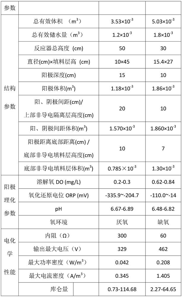
[0064] For the comprehensive sewage of COD=0-1000mg / L concentration scope, adopt the structure among the present invention, compare the electrochemical performance of CW-MFC system under different A values, the result is as shown in table 1: relative to A=0.75, A= 1, the electrical performance parameters of the system are:

[0065] 1) The maximum output voltage is increased by 40.4% to 1.2 times, the maximum current density is increased by 2.03 times, the maximum power density is increased by 4.26 times, and the internal resistance is reduced by 80%;

[0066] 2) The richness of the dominant electrogenic bacterium Geobacter (Geobacter) enriched at the anode increased by 10.2 times, and the richness of Geothrix (Geothrix) increased by 9.93 times;

[0067] 3) The abundance of the dominant denitrification bacteriu...


PUM

PropertyMeasurementUnit
particle diameteraaaaaaaaaa
thicknessaaaaaaaaaa
thicknessaaaaaaaaaa

Abstract

The invention discloses a vertical flow artificial wetland structure and configuration method for improving electric energy capture in the sewage purification process. The steps are: A. filling a non-conductive filler layer at the bottom of the vertical flow artificial wetland; B. filling the upper part of the non-conductive filler layer Filling the anode conductive filler layer; C, filling the non-conductive filler isolation layer above the anode conductive filler layer; D, setting the cathode conductive filler layer on the surface of the non-conductive filler isolation layer, and setting the cathode collector in the cathode conductive filler layer; E, controlling The ratio of the volume of the anode filler layer to the volume of the non-conductive filler isolation layer; F, the sewage enters the non-conductive, anode, non-conductive, and cathode conductive filler layers from the bottom in turn; G, when the sewage flows through the system, the electrical energy converted from organic matter passes through the external Wire output. The structure is laid with bottom non-conductive, anode conductive, non-conductive and cathode conductive filler layers from bottom to top. It significantly improves the electric energy capture and output capacity of the vertical flow constructed wetland in the sewage purification process.

Description

technical field [0001] The invention belongs to the field of environmental protection, and in particular relates to a vertical flow artificial wetland structure for improving electric energy capture in the sewage purification process. At the same time, it also relates to a configuration method of a vertical flow artificial wetland for improving electric energy capture in the sewage purification process. The structure can capture and output electric energy to the maximum extent according to the concentration range of organic matter in the influent. Background technique [0002] Microbial fuel cell (MFC) has become a new hot spot in the field of sewage treatment because of its good performance in converting organic matter into electrical energy. Restricted by internal resistance, electrode materials and other factors, the scale of MFC is currently difficult to scale up, and most of them remain in the laboratory research stage, which limits its practical application. However, ...

Claims


Application Information

Patent Timeline
Patent Type & Authority Patents(China)
IPC IPC(8): C02F3/32C02F101/30
CPCC02F3/005C02F3/32C02F2101/30
Inventor 肖恩荣鲁汭吴振斌贺锋陈迪松陈宇华李志伟
Owner INST OF AQUATIC LIFE ACAD SINICA
Learn More