
Nitrogen sealing system and method for turbo expander with function of bearing box cooling

A turboexpander, nitrogen sealing technology, applied in mechanical equipment, engine components, machines/engines, etc., can solve the problem of difficult to take into account the cooling of gas turbine sealed bearing boxes, etc. Service life, the effect of prolonging the service life

Pending Publication Date: 2020-08-07
XIAN SHAANGU POWER
View PDF0 Cites 2 Cited by
  • Summary
  • Abstract
  • Description
  • Claims
  • Application Information

AI Technical Summary

Problems solved by technology

[0005] Aiming at the deficiencies in the prior art, the object of the present invention is to provide a nitrogen sealing system and method for a turbo expander with cooling of the bearing box, so as to solve the problem that it is difficult to balance the sealing and the bearing box of the gas turbine in the prior art. The technical problem of cooling

Method used


Image

  • Nitrogen sealing system and method for turbo expander with function of bearing box cooling

Examples


Embodiment 1

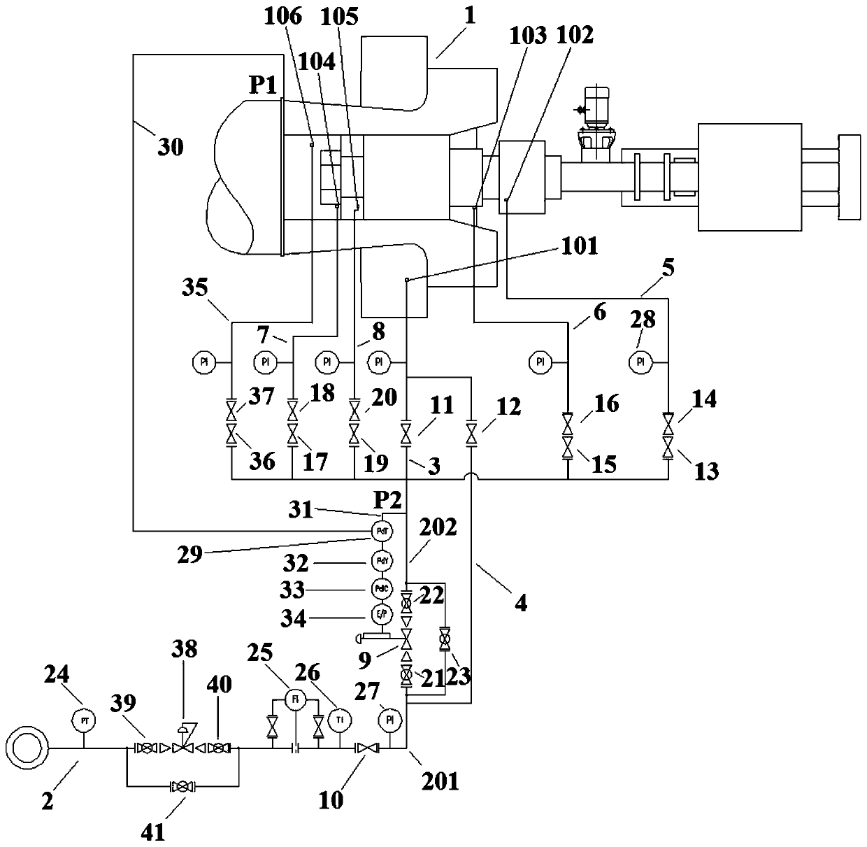
[0042] This embodiment provides a nitrogen sealing system for a turboexpander with cooling of the bearing box, such as figure 1 As shown, it includes a turboexpander 1, and the turboexpander 1 is provided with a nitrogen filling port 101 for the vane adjustment chamber, a carbon ring seal nitrogen filling port 102 on the intake side, a labyrinth seal nitrogen filling port 103 on the intake side, and an exhaust Side carbon ring seal nitrogen filling port 104, exhaust side labyrinth seal nitrogen filling port 105 and exhaust side bearing box nitrogen filling port 106;

[0043] It also includes the main pipeline 2, the sealing pipeline of the stator blade adjustment chamber A 3, the sealing pipeline of the stator blade adjustment chamber B 4, the carbon ring sealing pipeline on the intake side 5, the labyrinth sealing pipeline on the intake side 6, the carbon ring on the exhaust side Sealing pipeline 7, exhaust side labyrinth sealing pipeline 8 and exhaust side bearing box coolin...

Embodiment 2

[0053] This embodiment provides a nitrogen sealing method for a turboexpander with cooling of the bearing box, which uses the nitrogen sealing system for the turboexpander with cooling of the bearing box in Example 1 to seal the turboexpander 1 The static vane adjustment cavity, the carbon ring seal on the intake side, the labyrinth seal on the intake side, the carbon ring seal on the exhaust side and the labyrinth seal on the exhaust side are filled with nitrogen to seal the bearing housing on the exhaust side of turbo expander 1. Nitrogen cooling.

[0054] Specifically, in this method, the pressure behind the regulating valve is 0.4-0.6MPa; the pressure behind the regulating valve is kept 20-30kPa higher than the pressure of the sealed gas, and the pneumatic pressure is adjusted according to the real-time detection value of the pressure behind the regulating valve and the pressure of the sealed gas. The membrane regulating valve 9 performs real-time adjustment, and the nitro...


PUM


Abstract

The invention provides a nitrogen sealing system and method for a turbo expander with the function of bearing box cooling. The system comprises a main pipeline, a static blade adjusting cavity A sealing pipeline, a static blade adjusting cavity B sealing pipeline, a gas inlet side carbon ring sealing pipeline, a gas inlet side labyrinth sealing pipeline, an exhaust side carbon ring sealing pipeline, an exhaust side labyrinth sealing pipeline and an exhaust side bearing box cooling pipeline. The system has both the sealing function and the bearing box cooling function, it can be guaranteed thata TRT runs efficiently for a long time, the leaking face and losses are reduced, the nitrogen consumption of a unit public and auxiliary system is greatly reduced, and the equipment running cost is reduced. Static blade adjusting cavities, a gas inlet side nitrogen charge port and an exhaust side nitrogen charge port of the turbo expander are subjected to combined sealing through nitrogen, it canbe further ensured that coal gas is not leaked when the turbo expander runs, operators can achieve operation safely on site, and meanwhile environment pollution can be avoided.

Description

technical field [0001] The invention belongs to the field of metallurgy and relates to a turbo expander, in particular to a nitrogen sealing system and method for a turbo expander with cooling of a bearing box. Background technique [0002] In the metallurgical industry, the blast furnace gas produced by blast furnace ironmaking first passes through the dust removal equipment, and then passes through the pressure reducing valve group to supply users, which greatly wastes the original pressure energy and heat energy in the blast furnace gas. In order to recover the energy lost in the blast furnace gas, it is necessary to increase the blast furnace gas residual pressure turbine power plant (TRT). It is used in dry and wet dedusting TRT, wet and dry dual-purpose TRT, common TRT, blast furnace blast and energy recovery unit (BPRT), sintering waste heat and blast furnace top pressure energy recovery combined generator set (STRT). The turbo expander is an essential device for ene...

Claims


Application Information

Patent Timeline
Patent Type & Authority Applications(China)
IPC IPC(8): F01D11/04F01D11/00F01D25/12F01D25/16
CPCF01D11/04F01D11/005F01D11/003F01D25/125F01D25/16
Inventor 贾江平周根标李付俊卢丹丹柳黎光裴大海邓建平杨岐平边山成刘拥军强科严伟博闵彦锋
Owner XIAN SHAANGU POWER
Learn More