Combined electric appliance partial discharge vibration detection method

A partial discharge and vibration detection technology, applied in the direction of instruments, measuring electricity, measuring devices, etc., can solve the problems of equipment failure, threat to the safety of operators, and emerge in an endless stream, and achieve the effect of high accuracy, convenient use and convenient movement.

Pending Publication Date: 2020-08-07
ELECTRIC POWER SCI & RES INST OF STATE GRID TIANJIN ELECTRIC POWER CO +2
View PDF0 Cites 0 Cited by
  • Summary
  • Abstract
  • Description
  • Claims
  • Application Information

AI Technical Summary

Problems solved by technology

[0003] Although the reliability of combined electrical appliances is strong, various faults emerge in endlessly with the continuous increase of usage. Due to the production, transportation, installation and operation of gas-insulated combined electrical appliances, high-voltage conductor protrusions, grounding shell protrusions, and insulators are generated. Insulation defects such as surface metal particles, air bubbles in the insulator, insulator cracks, free metal particles, and suspended electrodes; when the gas-insulated combined electrical appliance operates at rated voltage, partial discharges will occur at the insulation defects, which will cause continuous deterioration of the insulation system and eventually lead to equipment failure. Fault
Gas-insulated combined electrical appliances have a high voltage level and a large installation capacity. Once an accident occurs, it will affect the stable operation of the entire power system, causing huge economic losses and threatening the safety of workers.
[0004] Because the existing technology uses large-scale proprietary detection equipment for detection and because this partial discharge fault is very hidden and difficult to find when it first occurs, it cannot be detected by electrical measurement until an obvious discharge occurs

Method used


Image

  • Combined electric appliance partial discharge vibration detection method
  • Combined electric appliance partial discharge vibration detection method
  • Combined electric appliance partial discharge vibration detection method

Examples


Embodiment Construction

[0031] The present invention will be described in further detail below in conjunction with the accompanying drawings.

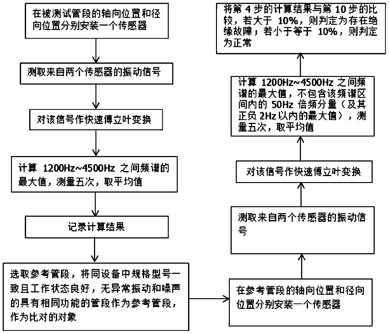
[0032] A method for detecting vibration of partial discharge of combined electrical appliances, such as figure 1 shown, including the following steps:

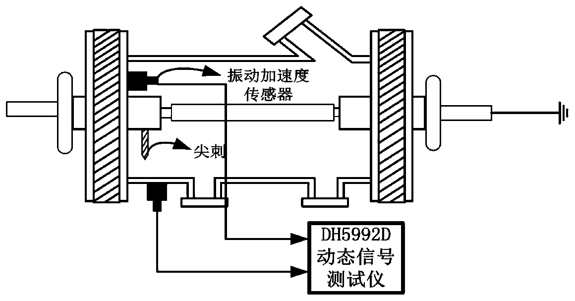
[0033] Step 1. Select a detection position on the pipe section to be tested, and install a vibration acceleration sensor on its axial and radial positions respectively.

[0034] In this step, the placement of the acceleration vibration sensor is based on the principle that the detected vibration signal is the strongest. After testing, the vibration signal detected at the flanges at both ends of the gas chamber is weak, and the vibration signal detected at the middle of the gas chamber is strong. Therefore, the vibration sensor is placed in the middle of a section of air chamber for detection. In addition, considering the difference between the vibration propagation direction and the vibration characteristi...


PUM


Abstract

The invention relates to a combined electric appliance partial discharge vibration detection method. The technical characteristic is that the method comprises: selecting detection positions on a tested pipe section and a reference pipe section; detecting a vibration signal by using an acceleration sensor; performing fast Fourier transform on the detected vibration signal and calculating the maximum amplitude of the frequency spectrum of the vibration signal; and comparing the maximum amplitude of the frequency spectrum of the vibration signal of the tested pipe section with the maximum amplitude of the frequency spectrum of the vibration signal of the reference pipe section, and judging whether the tested pipe section has a partial discharge fault or not, so that the effect of accurately detecting the partial discharge fault of the gas insulated switchgear is achieved. Equipment used in the method is small, use and moving are convenient, and accuracy is. The equipment is free of electrical connection with a tested pipe section and free of any influence on the running state of equipment, and by adding the vibration test technology into the electrical equipment fault diagnosis method, fault hidden dangers can be found earlier compared with an electrical detection electrical equipment fault diagnosis method.

Description

technical field [0001] The invention belongs to the technical field of fault diagnosis of power transmission and transformation equipment, in particular to a method for detecting partial discharge vibration of a combination electrical appliance. Background technique [0002] Gas-insulated combined electrical equipment is a complete set of electrical devices composed of a variety of high-voltage electrical installations, main wiring and system functions. It encapsulates common equipment in substations such as busbars, voltage transformers, current transformers, lightning arresters, isolating switches, circuit breakers, etc. through a cylinder filled with high-voltage SF6 insulating gas, so as to achieve strong system, high integration, It is one of the most important electrical equipment in high-voltage direct current engineering, and it is widely used in power systems of various voltage levels from 66 to 1000kV. [0003] Although the reliability of combined electrical appli...

Claims


Application Information

Patent Timeline
IPC IPC(8): G01R31/12
CPCG01R31/1209G01R31/1254
Inventor 屈斌韩斌王艳华王小朋王梓越王坤李国豪
Owner ELECTRIC POWER SCI & RES INST OF STATE GRID TIANJIN ELECTRIC POWER CO
Why Eureka
Try Eureka