Current collector and application thereof

A technology of current collector and metal layer, applied in current collector and its application field, can solve the problems of low connection yield and high contact resistance

Pending Publication Date: 2020-08-07
ZHUHAI COSMX BATTERY CO LTD
View PDF0 Cites 9 Cited by
  • Summary
  • Abstract
  • Description
  • Claims
  • Application Information

AI Technical Summary

Problems solved by technology

[0004] The invention provides a current collector, which is used to solve the problems of high contact resistance and low connection yield of tabs on the existing polymer / metal composite current collector

Method used


Image

  • Current collector and application thereof
  • Current collector and application thereof
  • Current collector and application thereof

Examples


Embodiment 1

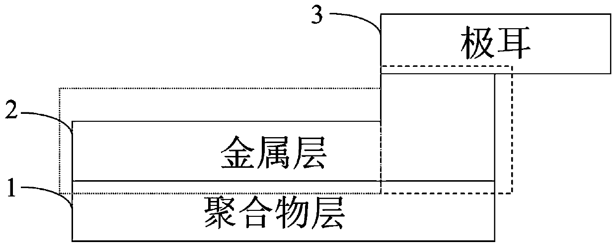
[0049] The current collector structure provided by this embodiment is as figure 1 As shown, the polymer layer is PET, the metal layer is aluminum, the thickness of the polymer PET layer is 6 μm, the thickness of the metal layer in the non-tab connection area is 1 μm, and the thickness of the metal layer in the tab connection area is 1.05 μm. The positive tab is welded on the tab connection area of ​​the metal aluminum layer by ultrasonic welding, the thickness of the positive tab is 0.1mm, and the width is 6mm;

[0050] Use the LK-108A model tensile tester of Likong Instrument Technology Co., Ltd. to clamp the tab with a clamp, and then use the tensile tester to test the pulling force N that the tab is pulled off from the current collector. The width of the tab is D, which can be The tab welding strength F=N / D is calculated, and the result shows that the tab welding strength in this embodiment is 0.6 N / mm.

Embodiment 2

[0052] The current collector structure provided by this embodiment is as figure 1 As shown, the polymer layer is PET, the metal layer is aluminum, the thickness of the polymer PET layer is 6 μm, the thickness of the metal layer in the non-tab connection area is 1 μm, and the thickness of the metal layer in the tab connection area is 1.5 μm. The positive tab is welded on the tab connection area of ​​the metal aluminum layer by ultrasonic welding, the thickness of the positive tab is 0.1mm, and the width is 6mm;

[0053] Using the same welding strength test method as in Example 1, the results show that the tab welding strength in this example is 1.1 N / mm.

Embodiment 3

[0055] The current collector structure provided by this embodiment is as figure 1 As shown, the polymer layer is PET, the metal layer is aluminum, the thickness of the polymer PET layer is 6 μm, the thickness of the metal layer in the non-tab connection area is 1 μm, and the thickness of the metal layer in the tab connection area is 2 μm. The way of welding is to weld the positive tab on the tab connection area of ​​the metal aluminum layer, the thickness of the positive tab is 0.1mm, and the width is 6mm;

[0056] Using the same welding strength test method as in Example 1, the results show that the tab welding strength in this example is 1.6 N / mm.


PUM

PropertyMeasurementUnit
strengthaaaaaaaaaa
thicknessaaaaaaaaaa
thicknessaaaaaaaaaa

Abstract

The invention provides a current collector and application thereof. The first aspect of the invention provides a current collector. The current collector comprises M metal layers and N polymer layers,the metal layers and the polymer layers are stacked, L metal layers comprise tab connecting areas and non-tab connecting areas, the thickness of the tab connecting areas is greater than that of the non-tab connecting areas, and M is greater than or equal to 1, N is greater than or equal to 1, L is greater than or equal to 1, and M is greater than or equal to L. According to the current collectorprovided by the invention, the tab connecting areas for connecting the tab on the metal layer is thickened, so that the welding strength of the tab is effectively improved, the binding force of the tab and the current collector is improved, the contact impedance of the tab connecting region is reduced, and the connecting yield of the tab and the metal layer is improved.

Description

technical field [0001] The invention relates to a current collector and its application, and relates to the technical field of lithium ion batteries. Background technique [0002] Due to its high energy density and high power density, lithium-ion batteries are currently a very versatile secondary battery. Conventional lithium-ion battery current collectors use metal foil, the positive electrode usually uses metal aluminum foil, and the negative electrode usually uses metal copper foil. Once the lithium-ion battery prepared directly using the metal foil has an internal short circuit, the current cannot be cut off inside the battery, resulting in Heat buildup eventually triggers thermal runaway. In order to solve this problem, some researchers have used a new type of polymer / metal composite current collector to replace the conventional metal current collector. This type of current collector usually uses a non-conductive polymer film as the substrate, and the upper and lower s...

Claims


Application Information

Patent Timeline
Patent Type & Authority Applications(China)
IPC IPC(8): H01M4/66H01M2/26H01M10/0525H01M50/531
CPCH01M4/667H01M10/0525H01M50/531Y02E60/10H01M50/536
Inventor 赵伟李素丽李俊义徐延铭
Owner ZHUHAI COSMX BATTERY CO LTD
Why Eureka
Try Eureka