Quasi-differential lock control system, differential rate control system and method and automobile

A technology of control system and differential lock, which is applied in the direction of control system, electric vehicle, control drive, etc., can solve the problem of lower efficiency, differential speed control that cannot be realized by differential gear and differential lock, resource consumption of rare earth shortage and mining and processing environmental issues

Active Publication Date: 2020-08-07
佛山中锦微电科技有限公司
View PDF11 Cites 0 Cited by
  • Summary
  • Abstract
  • Description
  • Claims
  • Application Information

AI Technical Summary

Problems solved by technology

[0003] ①The mechanical differential is relatively bulky, which increases the difficulty of vehicle load design and is not conducive to vehicle lightweight
[0004] ②The use of mechanical differential has insertion loss, which reduces the efficiency of mechanical energy transmission and increases the noise of the wheel train
[0005] ③Existing differentials cannot be locked, and a few differentials equipped with differential locks have complex structures, such as friction plates, which are prone to wear and heat during work, shortening maintenance cycles, increasing maintenance costs, and increasing failure rates
[0006] ④ Existing mechanical differentials and differential locks cannot achieve differential speed control
[0007] ⑤ The cost of existing mechanical differentials and differential locks is relatively high, while the hub motor control system is too complicated and the technology is immature
[0008] ⑥For permanent magnet motor vehicles, there are problems of high cost, complex control, thermally induced demagnetization and secondary battery loss
[0009] ⑦The use of permanent magnet motors in the industry chain still has consumption of scarce rare earth resources and environmental protection problems in the mining and processing process
[0010] In addition, it is about changing the motor into a differential motor structure design with internal and external dual rotors. This design is to connect the inner rotor to an output shaft to drive one wheel, and then connect the outer rotor to another output shaft to drive the other wheel after the gear is reversed. One wheel, or the outer rotor is connected to an output shaft to drive a wheel, and the inner rotor is connected to another output shaft to drive another wheel after the gear is reversed, so that the output shafts of the inner and outer rotors turn in the same direction, and the force between the inner and outer rotors is the driving force of the motor , although the differential effect can be realized, this structure cannot realize the differential lock function, and one side needs a reverse mechanism to participate in the operation, which reduces efficiency, increases structure, increases weight, increases production costs, and increases maintenance costs. The rotational momentum of the inner and outer rotors is difficult to be consistent, which will lead to an imbalance in the rotational momentum of the driving wheels on both sides, and there is a risk of steering, so it has not been practically applied

Method used


Image

  • Quasi-differential lock control system, differential rate control system and method and automobile
  • Quasi-differential lock control system, differential rate control system and method and automobile
  • Quasi-differential lock control system, differential rate control system and method and automobile

Examples


Embodiment 1

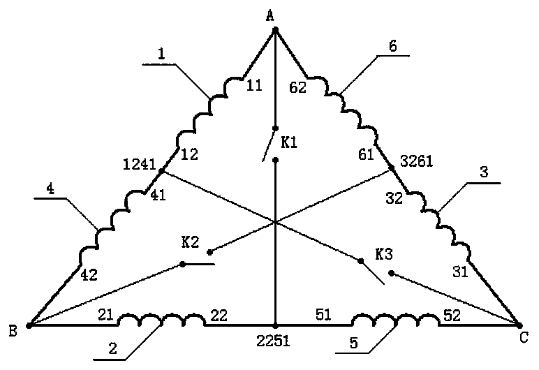
[0175] This embodiment provides a quasi-differential lock control system including two motors. Such as figure 1 As shown, it is a schematic diagram of a centerline differential lock connection method of a quasi-differential lock control system including two motors.

[0176] The two three-phase AC motors that the quasi-differential speed control system has are respectively the first motor and the second motor, and the three-phase windings that the first motor has are the first winding (1), the second winding (2) and the third winding ( 3), the first and last two terminals of the first winding (1) are respectively 11 and 12, the first and last two terminals of the second winding (2) are respectively 21 and 22, and the first and last two terminals of the third winding (3) are respectively 31 and 32, the three-phase windings of the second motor are the fourth winding (4), the fifth winding (5) and the sixth winding (6), and the first and last terminals of the fourth winding (4) ...

Embodiment 2

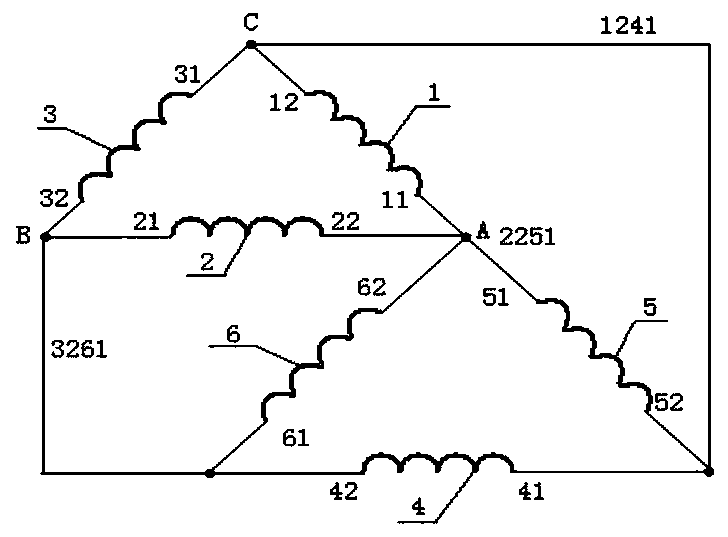
[0191] This embodiment provides a quasi-differential lock control system including three motors, such as Figure 5 and Figure 6 As shown, the three three-phase AC motors of the quasi-differential speed control system are respectively the first motor, the second motor and the third motor.

[0192] The three-phase windings of the first motor are the first winding (1), the second winding (2) and the third winding (3). The first and last terminals of the first winding are 11 and 12 respectively, and the first and last terminals of the second winding are two The terminals are 21 and 22 respectively, and the first and last terminals of the third winding are 31 and 32 respectively.

[0193] The three-phase windings of the second motor are the fourth winding (4), the fifth winding (5) and the sixth winding (6), the first and last two terminals of the fourth winding are 41 and 42 respectively, and the first and last two terminals of the fifth winding The terminals are 51 and 52 resp...

Embodiment 3

[0205] This embodiment provides a quasi-differential lock control system including four motors. Such as Figure 7 and Figure 8 As shown, the four three-phase AC motors are respectively the first motor, the second motor, the third motor and the fourth motor.

[0206] The three-phase windings of the first motor are the first winding (1), the second winding (2) and the third winding (3). The first and last terminals of the first winding are 11 and 12 respectively, and the first and last terminals of the second winding are two The terminals are 21 and 22 respectively, and the first and last terminals of the third winding are 31 and 32 respectively.

[0207] The three-phase windings of the second motor are the fourth winding (4), the fifth winding (5) and the sixth winding (6), the first and last two terminals of the fourth winding are 41 and 42 respectively, and the first and last two terminals of the fifth winding The terminals are 51 and 52 respectively, and the first and la...


PUM


Abstract

All windings of n three-phase alternating-current motors are connected end to end according to a motor sequence after phase splitting to obtain three edges belonging to three phases; the three edges are connected end to end to form a large triangle; the end-to-end connection points of the adjacent windings in each side are n equal division points of the side; each vertex of the large triangle is electrically connected with one n equal division point corresponding to the opposite side to form an equal division center line, two parts cut from the large triangle are equivalent to two new small triangles in electrical connection relation after the three equal division center lines are connected, and the vertexes of the small triangles coincide with the three vertexes of the large triangle; three vertexes are connected with a three-phase alternating current power supply, the motors in the small triangles are still kept in the same rotating direction when the large triangle runs, the three equal division center lines are connected to realize a quasi differential lock function among the motors, the differential function of back-load inductive voltage distribution is realized when the three equal division center lines are disconnected, and the phase sequence connection relationship is called as a neutral line theorem of the three-phase alternating current motor; and the difference rategamma can be modulated through the on-line switch conduction rate Cy.

Description

technical field [0001] The invention belongs to the technical field of motor and new energy vehicle electric drive system control, and relates to a quasi-differential lock and differential speed control system, a control method and a vehicle. Background technique [0002] The electric drive system with the motor as the core is widely used in various control fields, especially for electric drive vehicles. However, existing electrically driven vehicles include devices such as battery units, drive motors, electronic control systems, and differentials. Whether it is a fuel vehicle, a hybrid or a pure electric vehicle, the differential configured basically follows the traditional A mechanical differential is used to accommodate the speed difference between the two drive wheels. This has the following negative problems. [0003] ①The mechanical differential is relatively bulky, which increases the difficulty of vehicle load design and is not conducive to vehicle weight reduction...

Claims


Application Information

Patent Timeline
Patent Type & Authority Applications(China)
IPC IPC(8): H02K16/00B60K1/02
CPCH02P25/184H02P25/18H02P25/188H02P5/46H02P5/50B60L15/20B60L15/2036Y02T10/62Y02T10/64Y02T10/72
Inventor 杨明
Owner 佛山中锦微电科技有限公司
Why Eureka
Try Eureka