Tank type single-nozzle refining furnace and vacuum refining method

A single-mouth refining furnace and tank-type technology, applied in the field of tank-type single-mouth refining furnace and vacuum refining, can solve the problems of increasing the cooling frequency of vacuum tanks, reducing steel output, and high plant height, reducing vacuum processing time and reducing cleaning. The number of times, the effect of enhancing the refining effect

Active Publication Date: 2020-08-11
赵元庆 +1
View PDF3 Cites 3 Cited by
  • Summary
  • Abstract
  • Description
  • Claims
  • Application Information

AI Technical Summary

Problems solved by technology

[0004] The disadvantages of the RH furnace are: 1. The equipment is complex and expensive; 2. The height of the factory building is required to be high; 3. The molten steel in the vacuum chamber is seriously splashed; 4. The service life of the dipping tube is short; 5. The cost of vacuum treatment is high
[0005] The disadvantages of VD\VOD are: 1. Less steel tapping, 2. Serious slag overflow, and 3. Long vacuum treatment time; the reason is that the molten steel in the ladle will violently boil when the existing VD\VOD furnace is working. The slag overflows and splashes into the vacuum tank outside the ladle. On the one hand, this will cause the temperature of the vacuum tank to be too high, which will increase the cooling frequency of the vacuum tank, and also put forward higher requirements for cooling equipment. On the one hand, it will cause the steel slag in the vacuum tank to increase too quickly, so that the vacuum tank needs to be cleaned frequently, which increases the labor intensity of the workers and reduces the VD\VOD operation rate; The headroom is increased to 800-1200mm, and the amount of argon blowing per unit time is also reduced, which will reduce the amount of steel tapping in a steelmaking furnace, thereby reducing the steel output, and will also increase the vacuum refining time, making it comparable to the above Poor connection of downstream processes

Method used


Image

  • Tank type single-nozzle refining furnace and vacuum refining method
  • Tank type single-nozzle refining furnace and vacuum refining method
  • Tank type single-nozzle refining furnace and vacuum refining method

Examples


Embodiment Construction

[0047] To make the objectives, technical solutions, and advantages of the embodiments of the present invention clearer, the technical solutions in the embodiments of the present invention will be described clearly and completely in conjunction with the accompanying drawings in the embodiments of the present invention. Obviously, the described embodiments are part of the embodiments of the present invention, rather than all of the embodiments. Based on the embodiments of the present invention, all other embodiments obtained by those of ordinary skill in the art without creative work shall fall within the protection scope of the present invention.

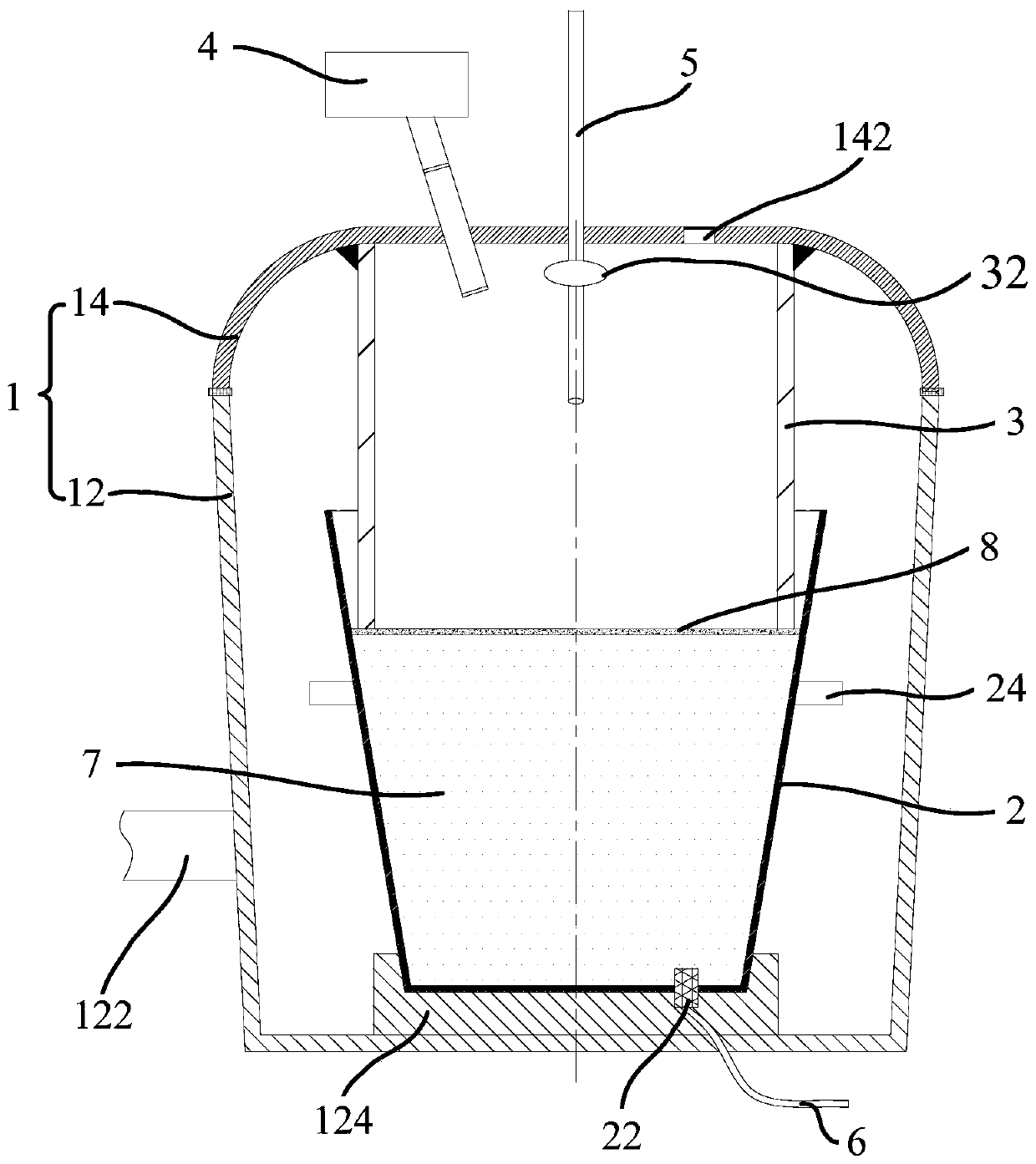
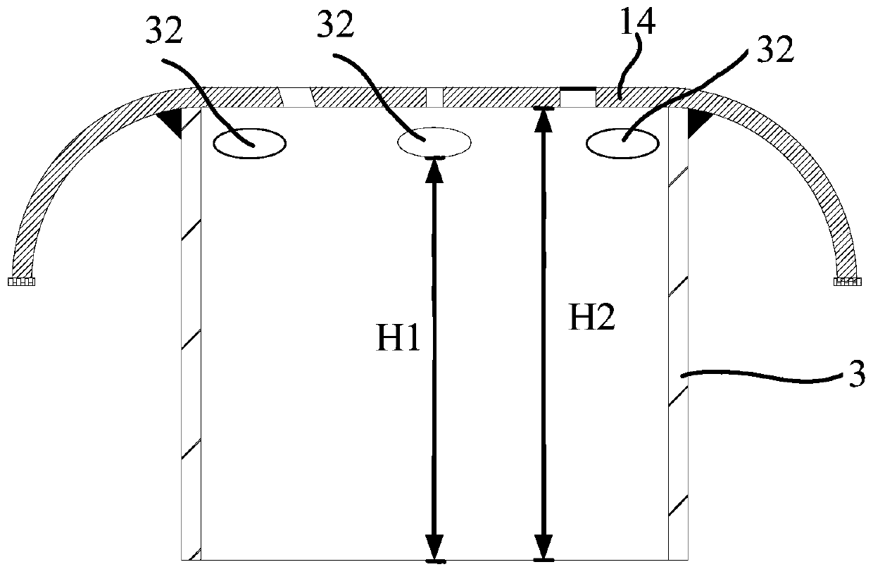
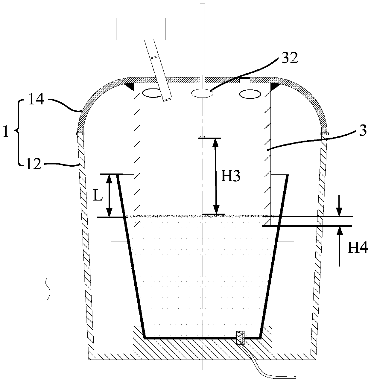
[0048] Refer below Figure 1 to Figure 4 To describe the tank-type single-mouth refining furnace provided by the embodiment of the present invention.

[0049] Such as Figure 1 to Figure 4 As shown, the first aspect of the present invention proposes a tank-type single-nozzle refining furnace. The tank-type single-nozzle refining furnace i...


PUM

PropertyMeasurementUnit
heightaaaaaaaaaa

Abstract

The invention provides a tank type single-nozzle refining furnace and a vacuum refining method. The tank type single-nozzle refining furnace comprises a vacuum tank and a single-nozzle dipping pipe, wherein the vacuum tank consists of a vacuum tank body and a vacuum tank cover; a vacuum air extracting pipeline is arranged on the vacuum tank body; a steel ladle containing molten steel to be treatedcan be placed in the vacuum tank; one end of the single-nozzle dipping pipe is integrated with the vacuum tank cover; after the steel ladle is hung in the vacuum tank, the lower end of the single-nozzle dipping pipe can extend into the steel ladle when the vacuum tank cover is lowered; and a vent hole for communicating the dipping pipe with the vacuum tank is formed in the upper end of the single-nozzle dipping pipe. In the scheme, the dipping pipe covers above the molten steel or is inserted into the molten steel, so that when slag overflow or molten steel splashing occurs in the dipping pipe, the slag overflow or the molten steel is prevented from being separated from the steel ladle to enter the vacuum tank body, the pollution to the vacuum tank body can be reduced, the steel tapping amount of a primary steel-making furnace can be increased, and the steel yield is further increased; and meanwhile, the argon blowing amount can be increased, the refining effect is enhanced, the refining efficiency is improved, the tank type single-nozzle refining furnace is better linked with the primary steel-making furnace and a subsequent continuous casting process, and the smoothness and continuity of each process are guaranteed.

Description

Technical field [0001] The invention relates to the technical field of iron and steel metallurgy, and more specifically, to a tank-type single-nozzle refining furnace and a vacuum refining method. Background technique [0002] In steel smelting, in order to meet the requirements of the purity of special steel, the molten steel in the primary steelmaking furnace needs to be refined to remove impurities in the molten steel and homogenize the alloying elements and temperature in the molten steel. The most common way to achieve the above purpose is to vacuum process the molten steel, such as degassing the molten steel (hydrogen, oxygen, nitrogen), desulfurization, decarburization or deep decarburization, etc.; in degassing the molten steel , In the process of decarburization, add appropriate amount of alloy and stir the molten steel according to the requirements of different steel grades, promote the homogenization of alloy and temperature, and make the harmful inclusions in the molt...

Claims


Application Information

Patent Timeline
Patent Type & Authority Applications(China)
IPC IPC(8): C21C7/10C21C7/072C21C7/068C21C7/064C21C7/06
CPCC21C7/10C21C7/072C21C7/068C21C7/064C21C7/06
Inventor 赵元庆李道明郭汉杰刘良田赵勇
Owner 赵元庆
Why Eureka
Try Eureka