
Airless rear-mounted w-flame boiler with secondary air nozzles on the arch and air distribution method

A secondary air and air nozzle technology, applied in the field of boiler combustion, can solve the problems of late ignition of pulverized coal airflow, slagging, and low level of air classification

Active Publication Date: 2021-07-06
HARBIN INST OF TECH
View PDF6 Cites 0 Cited by
  • Summary
  • Abstract
  • Description
  • Claims
  • Application Information

AI Technical Summary

Problems solved by technology

Most of the secondary air is fed into the furnace under the arch, and the pulverized coal is burned in an oxygen-rich environment, and the air classification level in the furnace is low, which is not conducive to suppressing the formation of fuel-type NOx
[0004] In summary, during the operation of FW-type W-flame boilers, there are generally problems such as high NOx emissions, late ignition of pulverized coal airflow, unstable combustion, and slagging of the front and rear walls.

Method used


Image

  • Airless rear-mounted w-flame boiler with secondary air nozzles on the arch and air distribution method
  • Airless rear-mounted w-flame boiler with secondary air nozzles on the arch and air distribution method
  • Airless rear-mounted w-flame boiler with secondary air nozzles on the arch and air distribution method

Examples


specific Embodiment approach 1

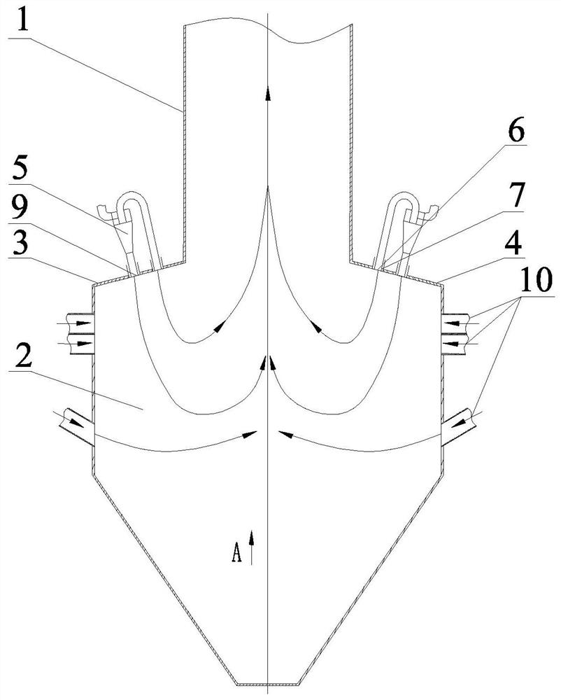
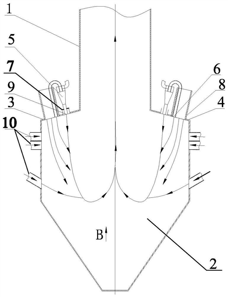
[0023] Embodiment 1: Combining image 3 and Figure 4 To illustrate this embodiment, the spent gas rear-mounted W-flame boiler with secondary air nozzles arranged on the arch in this embodiment includes an upper furnace 1, a lower furnace 2, a front furnace arch 3, a rear furnace arch 4, and two rows of double cyclone dense and light pulverized coal. The burner 5 and the secondary air nozzles 8 on the two rows of arches;

[0024] The upper furnace chamber 1 and the lower furnace chamber 2 are connected by the front furnace arch 3 and the rear furnace arch 4. The front furnace arch 3 and the rear furnace arch 4 are respectively provided with a row of double cyclone thick and light pulverized coal burners 5 and a row of secondary air nozzles on the arches. 8,

[0025] Each double cyclone rich and light pulverized coal burner 5 in each row of double cyclone rich and light pulverized coal burners 5 includes a spent gas nozzle 6, two peripheral air nozzles 7 and two rich pulveriz...

specific Embodiment approach 2

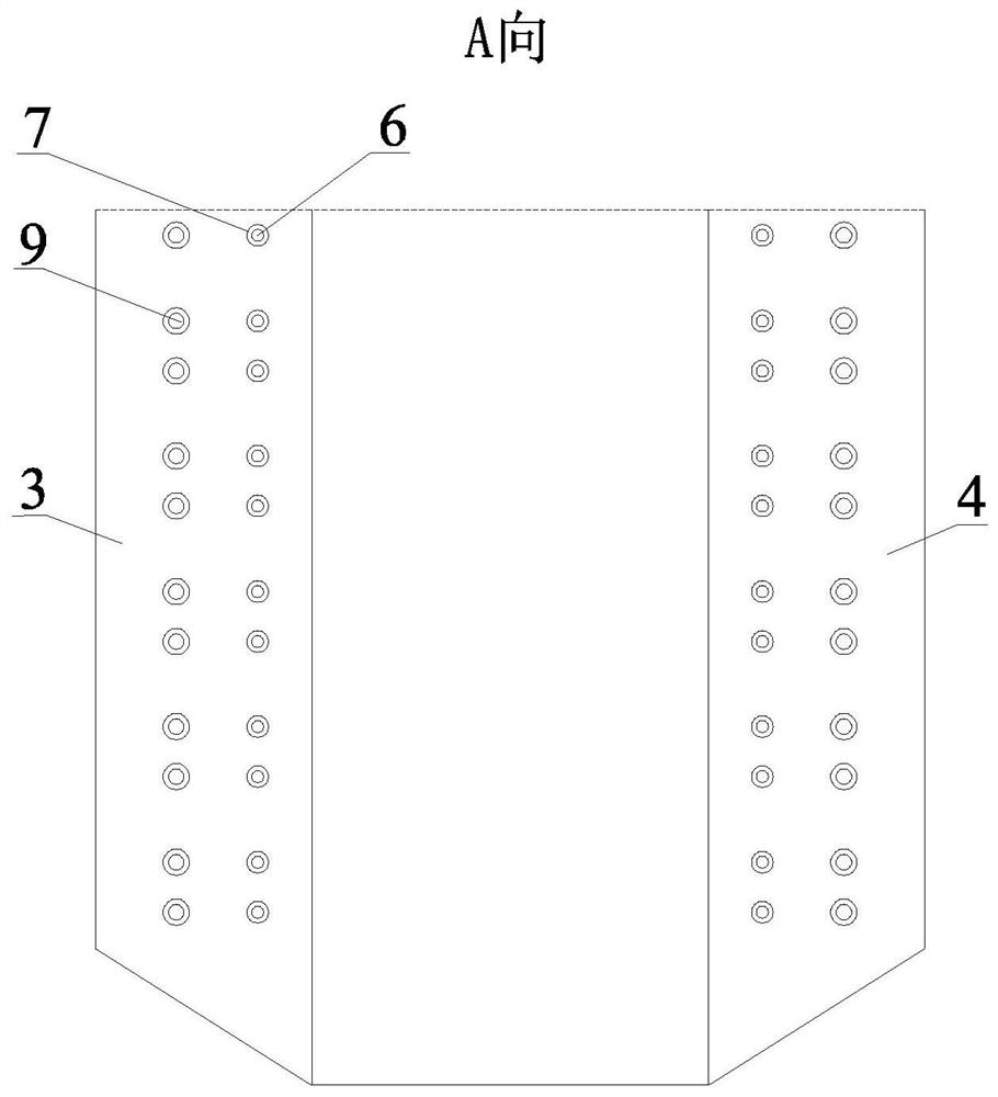
[0028] Specific implementation mode 2: Combining Figure 4 To illustrate this embodiment, in this embodiment, each exhausted gas nozzle 6 located on one side of the upper furnace 1 is arranged on the same side in the vertical direction of the centerline of the two rich pulverized coal gas flow nozzles 9 on each double cyclone rich and thin pulverized coal burner 5. on-line.

[0029] Other components and connection relationships are the same as in the first embodiment.

specific Embodiment approach 3

[0030] Specific implementation three: combination image 3 To illustrate this embodiment, in this embodiment, the secondary air nozzles 8 on each arch are arranged adjacent to the side wall of the lower furnace 2 .

[0031] Other components and connection relationships are the same as in the first embodiment.


PUM


Abstract

A post-exhaust W-flame boiler with an arched secondary air nozzle and an air distribution method, belonging to the technical field of boilers, to solve the problem of late ignition of the pulverized coal airflow of the double-cyclone dense and light pulverized coal burner W flame boiler, poor burnout and poor burnout. Unreasonable distribution of secondary air volume above and below the arch, low level of staged combustion in the furnace, and high NOx emissions. The invention includes a furnace body, two rows of double cyclone thick and thin pulverized coal burners, and secondary air nozzles on the arch; the two exhaust gas nozzles of each double cyclone tube burner are combined into one near secondary air nozzle arranged on the corresponding arch. At the center side of the furnace, the invention also proposes a combustion adjustment method for a W flame boiler using the secondary air on the arch and the exhaust air behind it. The invention optimizes the secondary air ratio of the boiler and reduces the NOx emission level of the boiler. At the same time, the reasonable arrangement of the thick and thin pulverized coal airflow is beneficial to promote the ignition and combustion of the pulverized coal airflow and prevent the slagging of the front and rear walls of the boiler.

Description

technical field [0001] The invention relates to a coal-fired power station boiler, in particular to a spent gas rear-mounted W flame boiler with secondary air nozzles arranged on an arch and an air distribution method, belonging to the technical field of boiler combustion. Background technique [0002] The W flame boiler is a power station boiler specially designed for burning low-volatile and refractory coal. It has the advantages of high furnace temperature and long combustion stroke of pulverized coal gas flow. W-flame boilers were introduced in Western Europe and other regions. Due to the abundant reserves of anthracite and lean coal resources in China, and the low price compared with other power coals, W-flame boilers were soon widely used and became one of the main furnace types for thermal power generation. At present, there are more than 130 W-flame boilers under construction or already under construction in China, with a total installed capacity of more than 41,000M...

Claims


Application Information

Patent Timeline
Patent Type & Authority Patents(China)
IPC IPC(8): F23C7/00F23L9/00F23K3/02
CPCF23C7/002F23K3/02F23L9/00
Inventor 李争起杜贺闫天舒郑智巍曾令艳陈智超
Owner HARBIN INST OF TECH
Learn More