Supercharge Your Innovation With Domain-Expert AI Agents!

Small hydraulic ash removal device

A hydraulic ash removal and hydraulic technology, which is applied in the field of ash removal from the combustion chamber, can solve the problems of limited installation area of ​​hydraulic soot blowers, low-load fire extinguishing of boilers, jamming of equipment transmission, etc., to achieve easy installation at any time and uniform water flow , layout flexible effect

Pending Publication Date: 2020-08-11
CHANGCHUN NO 2 CO GENERATION POWER
View PDF0 Cites 0 Cited by
  • Summary
  • Abstract
  • Description
  • Claims
  • Application Information

AI Technical Summary

Problems solved by technology

[0003] At present, the hydraulic sootblowers all use motors to drive the reducer gear (or chain), and the control switches of the program control system are used to drive the hydraulic sootblowers to run. Due to the high temperature working environment of the hydraulic sootblowers and the complex design of the equipment system, the equipment Defects such as jamming of the transmission part occur frequently, and the maintenance workload is relatively large; due to the large size of the equipment, the installation area of ​​the hydraulic soot blower is limited and it is not easy to install; the investment of a remote hydraulic soot blower can easily cause Water wall tube damage and boiler low-load fire extinguishing incidents have caused most thermal power plants to stop using

Method used


Image

  • Small hydraulic ash removal device
  • Small hydraulic ash removal device
  • Small hydraulic ash removal device

Examples


Embodiment 1

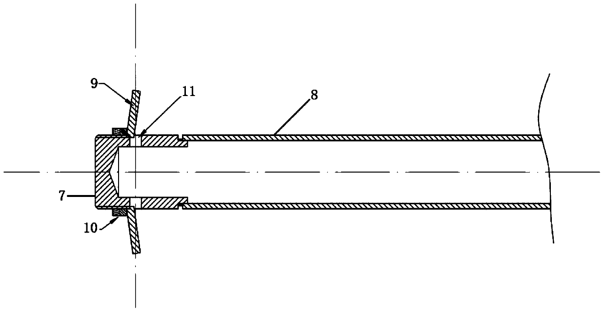
[0031] A small-sized hydraulic hydraulic ash removal device includes a spray gun body, which includes a gun body 1 , an outer cylinder body 4 and a water inlet pipe 5 .

[0032] Such as figure 1 As shown, the gun body 1 includes a gun head 7, a gun barrel 8 and an annular deflector 9, the gun head 7 is threadedly connected with the gun barrel 8, the gun head 7 is provided with a nozzle 11, and the annular guide vane 9 is arranged through a threaded connection Above the nozzle 11, the annular deflector 9 is used to control the angle of the water sprayed from the nozzle 11, and the back side of the annular deflector 9 is provided with

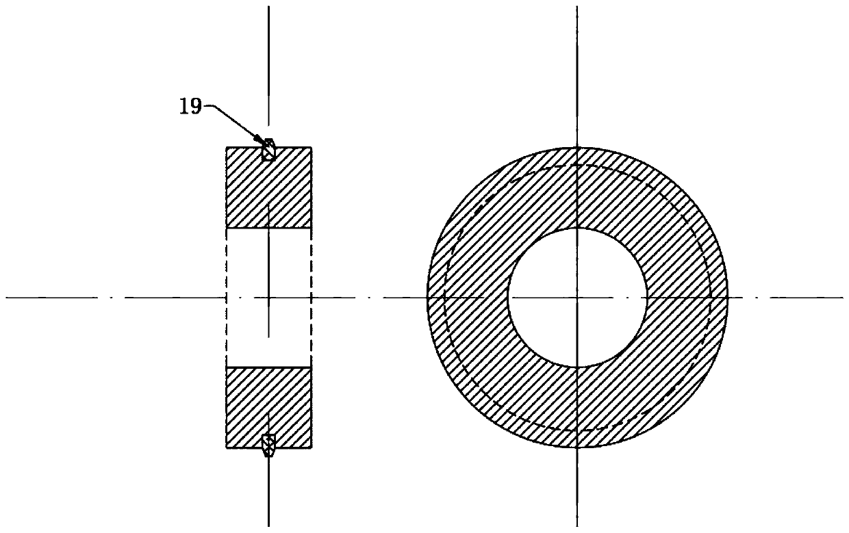
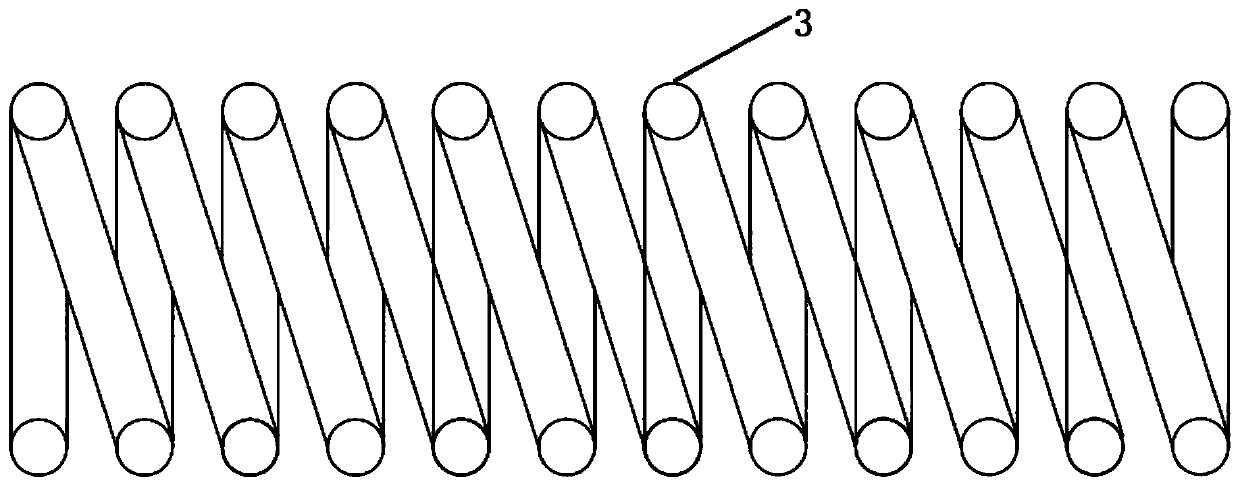
[0033] Such as figure 2 , image 3 , Figure 4 and Figure 5 As shown, the outer cylinder 4 includes a cylinder 12, a mounting flange 2 and a diameter flange 13, one end of the cylinder 12 is welded to the installation flange 2, and the other end of the cylinder is welded to the diameter flange 13; A compression spring 3 is arranged inside,...


PUM


Abstract

The invention belongs to the technical field of removal of ash from a combustion chamber, and particularly relates to a small hydraulic ash removal device. The small hydraulic ash removal device comprises a spraying gun body. The spraying gun body comprises a gun main body, an outer cylinder body and a water inlet pipe. The outer cylinder body comprises a cylinder main body, an installing flange and a diameter flange. The installing flange is welded to one end of the cylinder main body. The diameter flange is welded to the other end of the cylinder main body. A compression spring is arranged in the cylinder main body. One end of the compression spring abuts against the installing flange, and the other end of the compression spring is provided with a piston. The water inlet pipe comprises apipe body and an end side flange. The pipe body is welded to the end side flange. The gun main body penetrates through the center of the installing flange to be connected with the piston, so that thegun main body and the outer cylinder body are connected to form a work drum type structure. The diameter flange and the end side flange are connected through rubber ring sealing bolts so that the outer cylinder body and the water inlet pipe can be connected together. Water flow sprayed by the small hydraulic ash removal device covers a wide range of water-cooled wall, water flow is uniform, trajectory control is accurate, deslagging efficiency is high, and the small hydraulic ash removal device is a safe, reliable and mature boiler deslagging and decoking device.

Description

technical field [0001] The invention belongs to the technical field of removing ash from a combustion chamber, and in particular relates to a small hydraulic type hydraulic ash removal device. Background technique [0002] Accumulation of slag or coking on the heating surface of the water wall of the boiler will affect the heat transfer effect, increase the exhaust gas temperature, reduce the efficiency of the boiler, and even cause a tube burst accident in the superheater in severe cases. The hydraulic soot blower uses high-pressure water as the medium, and the water flow impacts on the ash deposits on the surface of the water wall tube, so that the ash and slag bonded to the heating surface of the water wall are removed due to sudden cooling, brittle cracking and loosening. [0003] At present, the hydraulic sootblowers all use motors to drive the reducer gear (or chain), and the control switches of the program control system are used to drive the hydraulic sootblowers to ...

Claims


Application Information

Patent Timeline
Patent Type & Authority Applications(China)
IPC IPC(8): F23J1/00
CPCF23J1/00
Inventor 朱廷旺郝哲晶刘庆峰朱浩庆高锋高洋
Owner CHANGCHUN NO 2 CO GENERATION POWER
Features
  • R&D
  • Intellectual Property
  • Life Sciences
  • Materials
  • Tech Scout
  • Unparalleled Data Quality
  • Higher Quality Content
  • 60% Fewer Hallucinations
Learn More