Multi-frequency composite high-power tile-type active phased array antenna

A phased array antenna, high-power technology, applied in antennas, antenna arrays, independent antenna unit combinations, etc. Requirements and other issues, to achieve the effect of keeping the antenna size small, low complexity, and improving affordability

Active Publication Date: 2020-09-22
成都雷电微力科技股份有限公司
View PDF8 Cites 0 Cited by
  • Summary
  • Abstract
  • Description
  • Claims
  • Application Information

AI Technical Summary

Problems solved by technology

With the increasingly complex wireless communication scenarios, the performance requirements of the active phased array antenna system are becoming more and more stringent. The active phased array antenna has changed from the previous single-frequency working mode to dual-frequency or even multi-frequency working mode. The density requirement has also been greatly improved. At present, the dual-frequency working mode is easier to realize in the brick-type active phased array antenna, but the dual-frequency (or multi-frequency) tile-type active phased array antenna is rarely heard.
Moreover, the existing tile-type active phased array antennas basically work in low-power single-frequency mode, and it is difficult to achieve high-integration high-power dual-frequency (multi-frequency) composite

Method used


Image

  • Multi-frequency composite high-power tile-type active phased array antenna
  • Multi-frequency composite high-power tile-type active phased array antenna
  • Multi-frequency composite high-power tile-type active phased array antenna

Examples


Embodiment 1

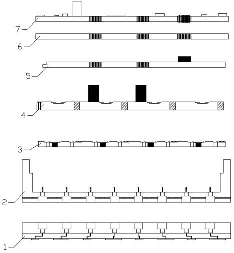
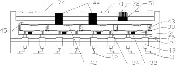
[0037] This embodiment discloses a multi-frequency composite high-power tile-type active phased array antenna, such as figure 1 As shown, it includes wave control power supply layer 7, cover plate layer 6, low frequency power supply transfer layer 5, radio frequency layer 4, radio frequency transfer layer 3, module cavity 2 and Array antenna layer 1; radio frequency layer 4 includes at least one radio frequency sublayer; as figure 2 As shown, the cover layer 6 seals the opening of the module cavity 2 , and seals the low-frequency power supply transfer layer 5 , the radio frequency layer 4 , and the radio frequency transfer layer 3 in the module cavity 2 .

[0038]The wave control power supply layer 7 is used to obtain external power, supply power to the low frequency power supply transfer layer 5 and send digital signals. The low-frequency power supply transfer layer 5 is connected to the wave-controlled power supply layer 7, and is used to obtain power supply and digital si...

Embodiment 2

[0057] Taking the radio frequency layer 4 as an example containing only one radio frequency sub-layer (multi-layers are the same), this embodiment discloses a multi-frequency composite high-power tile-type active phased array antenna, such as figure 1 As shown, it includes a wave control power supply layer 7, a cover layer 6, a low-frequency power supply transfer layer 5, a radio frequency layer 4, a radio frequency transfer layer 3, and a module cavity 2, which are arranged layer by layer from the RF signal excitation end to the antenna radiation end. and array antenna layer 1; such as figure 2 As shown, the cover layer 6 seals the opening of the module cavity 2 , that is, the low-frequency power supply transfer layer 5 , the radio frequency layer 4 and the radio frequency transfer layer 3 are all arranged in the cavity of the module cavity 2 .

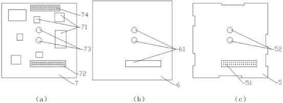
[0058] Such as figure 2 , image 3 As shown in (a), the side of the wave control power supply layer 7 away from the cover layer...

Embodiment 3

[0066] In this embodiment, Ka-band and Ku-band are taken as examples, and a 4*4 channel unit is taken as an example. This embodiment discloses a multi-frequency (dual-frequency) composite high-power tile-type active phased array antenna. It includes a wave control power supply layer 7, a cover layer 6, a low-frequency power supply transfer layer 5, a radio frequency layer 4, a radio frequency transfer layer 3, a module cavity 2 and an array antenna, which are arranged layer by layer from the RF signal excitation end to the antenna radiation end Layer 1; as in figure 2 As shown, the cover layer 6 seals the opening of the module cavity 2 , that is, the low-frequency power supply transfer layer 5 , the radio frequency layer 4 and the radio frequency transfer layer 3 are all arranged in the cavity of the module cavity 2 .

[0067]The microstrip antenna array 1 is composed of a sparsely distributed Ka antenna array (that is, the first antenna array 11) and a Ku antenna array (that...


PUM


Abstract

The invention discloses a multi-frequency composite high-power tile-type active phased array antenna, which comprises a layer-by-layer wave control power supply layer, a cover layer, a low-frequency power supply transfer layer, a radio frequency layer, a radio frequency transfer layer, and a module cavity and array antenna layers. The wave control power supply layer is used to obtain power, supply power to the lower layer and send digital signals. The low-frequency power supply transfer layer is used to supply power to the lower layer and send digital signals. Each radio frequency sub-layer and radio frequency transfer layer receive through the corresponding high-frequency connectors. The corresponding excitation signal, and preprocess the received excitation signal according to the digital signal; each RF sublayer will introduce the preprocessing result of the excitation signal into the RF transfer layer; the RF transfer layer will also preprocess the excitation signal in this layer The results, as well as the preprocessing results introduced by the radio frequency sub-layers of each layer, are respectively transmitted to the corresponding antenna units arranged on the array antenna layer, and a heat dissipation structure is arranged in the module cavity layer. The invention has the characteristics of multi-frequency, multi-channel, multi-polarization and high integration.

Description

technical field [0001] The invention relates to the field of microwave wireless communication, in particular to a multi-frequency composite high-power tile-type active phased array antenna. Background technique [0002] With the improvement of the performance of the phased array antenna system, the development of high-frequency materials and processes, and the progress of micro-assembly technology, the active phased array antenna front-end technology is gradually developing towards dual-frequency composite, small size, and high integration. At present, the active phased array antenna structure is mainly divided into brick integration and tile integration. The brick integration method is mostly used for high-power active phased array antennas, and the tile integration method is mostly used for low-power active phased array antennas. array antenna. With the increasingly complex wireless communication scenarios, the performance requirements of the active phased array antenna s...

Claims


Application Information

Patent Timeline
Patent Type & Authority Patents(China)
IPC IPC(8): H01Q21/30H01Q23/00H01Q1/02H01Q1/50H01Q21/00
CPCH01Q1/02H01Q1/50H01Q21/0006H01Q21/30H01Q23/00
Inventor 周沛翰薛伟冯琳符博丁卓富
Owner 成都雷电微力科技股份有限公司
Why Eureka
Try Eureka