A hydraulic automatic control system of a hydraulic shearing machine tool

An automatic control system, hydraulic technology, applied in the direction of fluid pressure actuation system components, accessories of shearing machines, shearing devices, etc., can solve problems such as out-of-synchronization of tool holders, out-of-synchronization of left and right, and severe vibration of machine tools, so as to avoid The effect of changing the shearing angle, prolonging the service life and avoiding violent vibration

Active Publication Date: 2021-09-17
宜兴市佳信数控科技有限公司
View PDF16 Cites 0 Cited by
  • Summary
  • Abstract
  • Description
  • Claims
  • Application Information

AI Technical Summary

Problems solved by technology

[0005] However, the two shear cylinders used in this technical solution are connected in parallel, and we know that in actual use, it is difficult to achieve absolute equality due to factors such as processing errors and seal leakage, which will cause the hydraulic shearing machine tool to work. If the left and right are not synchronized, the tool holder will be seriously out of sync, which will cause the shearing angle to change, and the tool holder will not be synchronized, which will affect the service life of the shearing machine and the cutter; Cut the cylinder down quickly, and then send a signal to the electrical system through the contact SQ2 to unload the first electromagnetic overflow valve to realize the slow down of the shear cylinder, but it suddenly changes from fast low pressure to slow high pressure, due to inertia, As a result, it is difficult to stop suddenly, the pulsation impact is large, and the vibration of the machine tool is severe, which further affects the service life of the hydraulic shearing machine tool and the cutter

Method used


Image

  • A hydraulic automatic control system of a hydraulic shearing machine tool
  • A hydraulic automatic control system of a hydraulic shearing machine tool
  • A hydraulic automatic control system of a hydraulic shearing machine tool

Examples


Embodiment approach

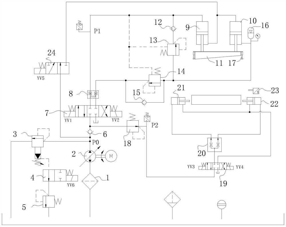
[0043] As a specific embodiment of the present invention, the control oil port of the pilot relief valve 3 communicates with the oil tank through the two-position two-way reversing valve 4 and the direct-acting relief valve 5 in sequence, and the two-position two-way reversing valve The directional valve 4 is normally closed, and the set pressure of the pilot relief valve 3 is greater than the set pressure of the direct-acting relief valve 5; it also includes a contact switch 23 matched with the two-position two-way reversing valve 4, and the The contact switch 23 sends a signal when it detects that the cutter 11 is in contact with the object to be cut and makes the two-position two-way reversing valve 4 de-energized; The reversing valve 4 is normally closed. At this time, the system pressure is the smaller set pressure of the direct-acting relief valve 5, which facilitates the rapid downward movement of the cutter 11 at low pressure; when the cutter 11 touches the object to be...


PUM


Abstract

The invention relates to the technical field of shearing machine tools, in particular to a hydraulic automatic control system of a hydraulic shearing machine tool. The hydraulic automatic control system includes a system overflow circuit, a series shear circuit and a decompression clamping circuit; the system The overflow circuit includes an oil inlet filter connected to the oil tank, and the oil inlet filter is sequentially connected to the oil pump and the first one-way valve through pipelines, and the pipelines of the oil pump and the first one-way valve pass through the pilot overflow valve and the first check valve. The oil tank is connected; the present invention can realize the first fast low-pressure downward movement of the cutter, then the slow-speed low-pressure downward movement, and finally the slow-speed high-pressure downward movement, so that it can change from fast to slow more smoothly, avoid violent shock during the transition, and prolong the hydraulic shearing time. The service life of the machine tool and the cutter; the overall synchronization can also be ensured through the shearing cylinder series connection and the setting of the compensation circuit, so as to avoid the serious out-of-synchronization of the tool holder and the change of the shearing angle, and further prolong the use of the shearing machine tool and the cutter life.

Description

technical field [0001] The invention relates to the technical field of shearing machine tools, in particular to a hydraulic automatic control system of a hydraulic shearing machine tool. Background technique [0002] The shearing machine tool is a kind of forging machine, which is a machine that uses a cutting knife to make a reciprocating linear motion relative to the other cutting knife to shear the plate. With the help of the moving upper cutter and the fixed lower cutter, the shearing machine adopts a reasonable cutter gap to apply shear force to the metal sheets of various thicknesses, so that the sheets are broken and separated according to the required size. At present, shearing machine tools are widely used in aviation, light industry, metallurgy, chemical industry, construction, shipbuilding, automobile, electric power, electrical appliances, decoration and other industries, providing the required special machinery and complete sets of equipment. [0003] Shearing ...

Claims


Application Information

Patent Timeline
Patent Type & Authority Patents(China)
IPC IPC(8): B23D15/14B23D33/02B23Q3/08F15B21/08F15B11/16
CPCB23D15/14B23D33/02B23Q3/082F15B11/16F15B21/087
Inventor 裴跃新裴杨朱佳琦
Owner 宜兴市佳信数控科技有限公司
Why Eureka
Try Eureka