Air film offshore wind power foundation structure prefabrication method

An infrastructure and offshore wind power technology, which is applied in infrastructure engineering, protection devices, buildings, etc., can solve the problems of reducing the prefabrication speed of tubular infrastructure, complex marine environment, and complex line shape, and achieves fast and efficient construction process. Durable, easy-to-manufacture effects

Inactive Publication Date: 2020-08-14
TIANJIN UNIV
View PDF5 Cites 0 Cited by
  • Summary
  • Abstract
  • Description
  • Claims
  • Application Information

AI Technical Summary

Problems solved by technology

[0004] However, at present, the method of prefabrication and construction of the bank of the cylindrical foundation is relatively simple, and traditional methods such as making special steel formwork are mostly used for the concrete pouring of the top cover of the cylindrical foundation and the transition section.
Since the transition section of the cylindrical foundation usually adopts the design of "small waist", its shape is relatively special, and the line shape is complicated. The design and manufacture of the formwork and the pouring of the concrete structure are more difficult, which reduces the difficulty of the cylindrical foundation to a certain extent. Prefabrication speed of structures
In addition, because the existing concrete pouring is traditional pouring, there is no effective protective layer or protection method for steel bars, and the marine environment is complex, and the internal steel bars of the concrete structure of the transition section and the cylindrical foundation are easily corroded, which seriously affects the overall structure The safety and stability of the operation process

Method used


Image

  • Air film offshore wind power foundation structure prefabrication method
  • Air film offshore wind power foundation structure prefabrication method
  • Air film offshore wind power foundation structure prefabrication method

Examples


Embodiment Construction

[0024] Such as Figure 1-6 The air film offshore wind power infrastructure prefabrication method shown includes the following steps:

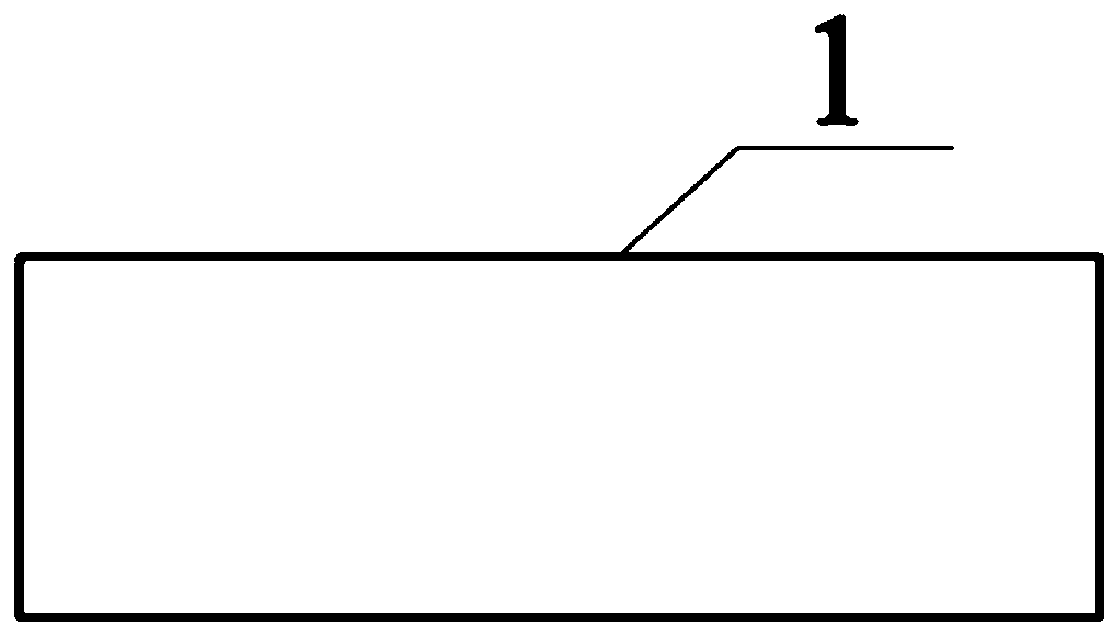
[0025] (1) Welding the steel cylinder wall and the internal compartment plate to make the prefabricated steel cylinder 1;

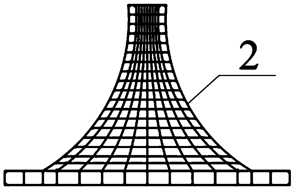
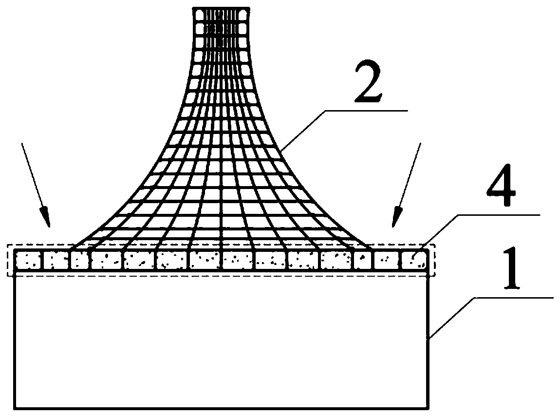
[0026] (2) Binding or welding steel bars, making steel cylinder top cover 4 and transition section reinforcement cage 2;

[0027] (3) Cover the steel cylinder top cover 4 on the prefabricated steel cylinder 1, and pour concrete for the steel cylinder top cover 4 by adopting the traditional formwork method;

[0028] (4) Carry out flexible air film 3 cutting, bonding, finish the skeleton making of flexible air film 3, flexible air film 3 is supported on the outside of transitional section reinforcing cage 2, make the top seal of transitional section reinforcing cage 2, then Inflate the interior of the steel cage 2 in the transition section;

[0029] (5) After inflating and finalizing the shape, spray a layer of cement mor...


PUM


Abstract

The invention provides an air film offshore wind power foundation structure prefabrication method. The air film offshore wind power foundation structure prefabrication method comprises the following steps of (1) welding a steel cylinder wall and an inner cabin plate to manufacture a prefabricated steel cylinder; (2) manufacturing a steel cylinder top cover and a transition section reinforcement cage; (3) pouring concrete to the steel cylinder top cover; (4) supporting a flexible air film on the outer side of the transition section steel reinforcement cage, sealing the top of the transition section steel reinforcement cage, and inflating the interior of the transition section steel reinforcement cage; (5) after inflation shaping, spraying a layer of cement mortar to the surface of the flexible air film on the inner side of the transition section reinforcement cage; spraying the concrete layer by layer from the inner side of the transition section reinforcement cage until all concrete issprayed; and (6) deflating the flexible air film, and detaching the part, not embedded into the concrete, of the flexible air film; concrete curing. According to the method, the strength of the outerside of the concrete is improved, and meanwhile the influence of seawater corrosion on steel bars is reduced.

Description

technical field [0001] The invention relates to the technical field of offshore wind power, and more specifically, to a method for prefabricating an air film offshore wind power infrastructure. Background technique [0002] Offshore wind power has the advantages of low turbulence, excellent wind resources, does not occupy cultivated land, and is close to developed coastal areas in my country. It has developed rapidly in recent years. Recently, a number of offshore wind farms have been built or are being built in the eastern waters of my country, and the installed capacity continues to rise. Therefore, fast and efficient construction, construction, and construction methods are key factors that will help future offshore wind power enter a stage of rapid development. [0003] In recent years, the research and application of composite tubular foundation structures has developed rapidly. Compared with traditional pile foundation structures, tubular foundations have significant ad...

Claims


Application Information

Patent Timeline
Patent Type & Authority Applications(China)
IPC IPC(8): E02D27/42E02D27/44E02D27/52E02D31/02
CPCE02D27/42E02D27/44E02D27/52E02D31/02
Inventor 练继建刘润燕翔练冲
Owner TIANJIN UNIV
Why Eureka
Try Eureka