Pneumatic high-speed cupping test device and system

A cupping test, high-speed technology, applied in measuring devices, devices that measure the time required to move a certain distance, radio wave measurement systems, etc., can solve problems such as insufficient air pressure, unstable impact speed, and difficulty in evaluating formability

Pending Publication Date: 2020-08-14
SHANDONG JIANZHU UNIV
View PDF9 Cites 2 Cited by
  • Summary
  • Abstract
  • Description
  • Claims
  • Application Information

AI Technical Summary

Problems solved by technology

[0003] The current standardized cupping test can measure the forming limit capability of metal sheets under quasi-static conditions, but the forming limit curves under quasi-static conditions are difficult to evaluate the formability at high strain rates
However, the cupping experiment under high strain rate has not been standardized yet, and there are ma

Method used


Image

  • Pneumatic high-speed cupping test device and system
  • Pneumatic high-speed cupping test device and system
  • Pneumatic high-speed cupping test device and system

Examples


Example Embodiment

[0039] Embodiment one:

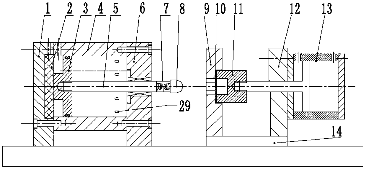
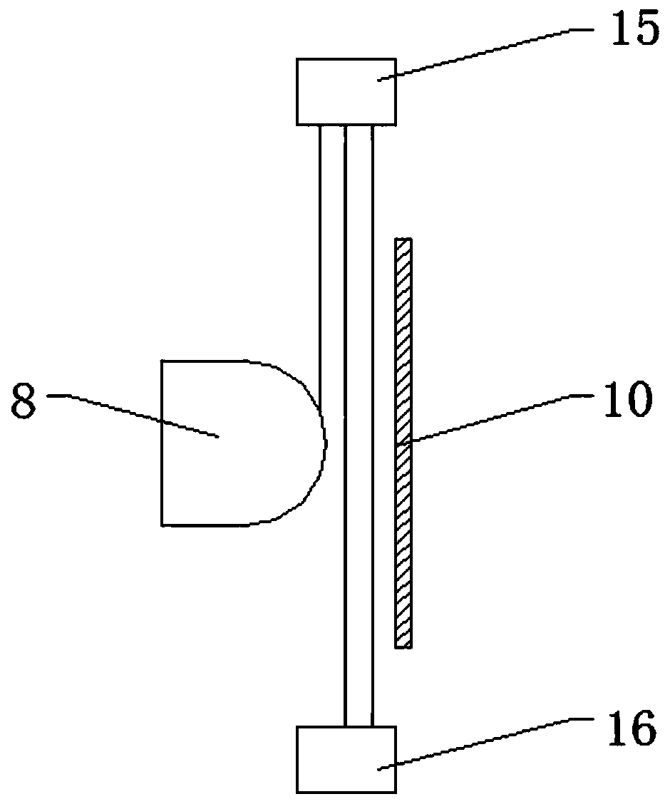
[0040] This embodiment provides a pneumatic high-speed cupping test device, including a punching device and a pressing device, such as figure 2 As shown, the punching device and the pressing device are arranged at a certain distance apart, and the distance between the two can be selected according to the impact depth requirements on the test piece 10 .

[0041] Specifically, the stamping device includes a cylinder 4, a first end cover 1, a second end cover 6, an electromagnet 2, a piston 3, a piston rod 5 and a punch 8, and one end of the cylinder 4 is detachably connected to the first end cover 1. , and the other end is detachably connected with the second end cover 6 . In this embodiment, the cylinder barrel 4 is connected with the first end cover 1 and the second end cover 6 through bolts.

[0042] The electromagnet 2 is fixed inside the cylinder barrel 4, and further, as shown in Figure 4 (a) and Figure 4 (b), the inside of the first end cover 1...

Example Embodiment

[0050] Embodiment 2:

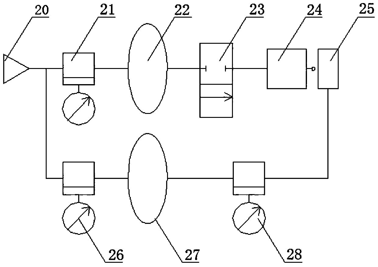
[0051] This embodiment provides a pneumatic high-speed cupping test system, including the test device described in the first embodiment, the punching device 24 and the pressing device 25 are respectively connected to the high-pressure air source 20 through pipelines.

[0052] Specifically, a first pressure regulating valve 21 , a first gas storage cylinder 22 , and a high-pressure solenoid valve 23 are sequentially installed on the pipeline connecting the high-pressure gas source 20 and the punching device 24 . The high-pressure gas source 20 is connected with the compression cylinder 13 through a pipeline, and a second pressure regulating valve 26 , a second gas storage cylinder 27 and an on-off valve 28 are installed on the pipeline in sequence.

[0053] The working principle of this embodiment is:

[0054] The high-pressure gas source 20 stores high-pressure gas, and outputs it to the first gas storage cylinder 22 through the first pressure regulatin...


PUM


Abstract

The invention discloses a pneumatic high-speed cupping test device and system. The pneumatic high-speed cupping test device comprises a stamping device and a pressing device, wherein the stamping device comprises a cylinder barrel, a piston is arranged in the cylinder barrel, and an electromagnet capable of adsorbing the piston is fixed in the cylinder barrel; the piston is connected with one endof the piston rod, the other end of the piston rod is fixedly provided with a punch; the pressing device and the stamping device are arranged in a spaced mode, the pressing device comprises a female die frame used for placing a test piece, a pressing air cylinder is installed on the side, which is away from the stamping device, of the female die frame, and the pressing air cylinder is connected with a pressing sleeve used for applying blank holder force to the test piece. According to the invention, a stable impact speed can be provided, the blank holder force of the test piece is controllable, and the impact force and the impact speed can be monitored in real time.

Description

technical field [0001] The invention relates to the field of impact tests, in particular to a pneumatic high-speed cupping test device and system. Background technique [0002] The cupping test is a test method for evaluating the formability of metal sheets. During the test, a spherical punch is used to push the pressed metal sheet into the die to form a bulge until cracks appear on the top of the bulge. The high-speed cupping test can detect the formability of metal sheets under high strain. Studies have proved that high strain rates can significantly improve the formability of various materials and reduce springback. [0003] The current standardized cupping test can measure the forming limit capability of metal sheets under quasi-static conditions, but the forming limit curves under quasi-static conditions are difficult to evaluate the formability under high strain rates. However, the cupping experiment under high strain rate has not yet been standardized, and there are ...

Claims


Application Information

Patent Timeline
IPC IPC(8): G01N3/307G01N3/06G01P3/68
CPCG01N3/307G01N3/068G01P3/68G01N2203/001G01N2203/0019G01N2203/0044G01N2203/006G01N2203/0676
Inventor 张莹张国庆原政军汤秀佳张坡
Owner SHANDONG JIANZHU UNIV
Why Eureka
Try Eureka