Method for designing and calculating drilling depth of medium-deep buried pipe geothermal heat exchanger

A technology of drilling depth and design calculation, which is applied in the field of design and calculation of drilling depth of geothermal heat exchangers in medium and deep underground pipes, and can solve the problems of small changes in rock and soil temperature, deep buried pipe, and high temperature at the bottom of the pipe.

Active Publication Date: 2020-08-14
SHANDONG JIANZHU UNIV
View PDF6 Cites 5 Cited by
  • Summary
  • Abstract
  • Description
  • Claims
  • Application Information

AI Technical Summary

Problems solved by technology

The depth of the traditional shallow ground source heat pump is within the range of 80m-150m, the rock and soil temperature changes little, and the influence of the temperature gradient is relatively small, so it is often not considered
However, the mid-to-deep ground source heat pump has the characteristics of deep buried pipe and high temperature at the bottom of the pipe. The ground temperature gradient has become an important factor affecting the heat extraction performance of the system, so the calculation model of the shallow heat exchanger is no longer applicable.
Most of the existing studies on mid-deep buried tube heat exchangers are based on estimating the drilling depth based on engineering experience, and then performing heat transfer simulation, heat extraction capacity evaluation, and operating energy consumption analysis on the system, and drilling the system for the known design heat load The problem of accurate design calculations at depth has not been resolved

Method used

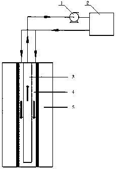
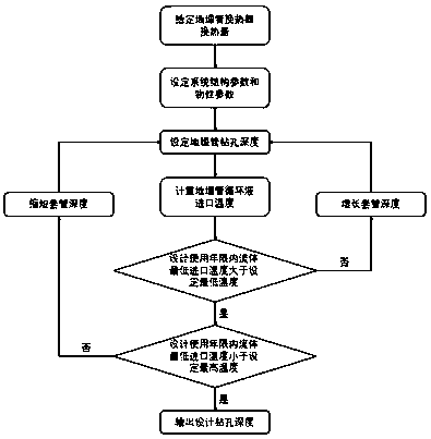
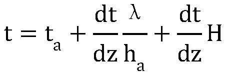

Image

  • Method for designing and calculating drilling depth of medium-deep buried pipe geothermal heat exchanger
  • Method for designing and calculating drilling depth of medium-deep buried pipe geothermal heat exchanger
  • Method for designing and calculating drilling depth of medium-deep buried pipe geothermal heat exchanger

Examples


Embodiment Construction

[0032] The present invention will be further described below in conjunction with the accompanying drawings and embodiments.

[0033] The structures, proportions, sizes, etc. shown in the drawings attached to this specification are only used to match the content disclosed in the specification for the understanding and reading of those who are familiar with this technology, and are not used to limit the conditions for the implementation of the present invention , so it has no technical substantive meaning, and any modification of structure, change of proportional relationship or adjustment of size shall still fall within the scope of the disclosure of the present invention without affecting the functions and objectives of the present invention. The technical content must be within the scope covered. At the same time, terms such as "upper", "lower", "left", "right", "middle" and "one" quoted in this specification are only for the convenience of description and are not used to lim...


PUM


Abstract

The invention discloses a method for designing and calculating the drilling depth of a medium-deep buried pipe heat exchanger, and the method comprises the steps: building a numerical heat exchange model on the basis of considering the ground temperature gradient, simulating the heat transfer process of a buried pipe, and carrying out the design and calculation of the drilling depth of the buriedpipe. Structural parameters of the buried pipe and physical property parameters of all parts of the system are known, the design and calculation of the drilling depth of the buried pipe according to the design thermal load are met, and the inlet water temperature of the buried pipe should be within a certain temperature range in the service life cycle of a building. According to the method, on thebasis that the designed thermal load is met, the designed drilling depth value is accurately calculated, and it is avoided that due to the fact that the designed drilling depth is small, the temperature of circulating liquid in the buried pipe is reduced, and the energy efficiency ratio of the heat pump unit is reduced; meanwhile, drilling cost waste caused by the fact that the drilling depth ofthe buried pipe is too large is avoided, data reference is provided for drilling design calculation of actual engineering, and in the actual engineering design process, the drilling design depth valuecan be obtained through calculation only by adjusting various parameters.

Description

technical field [0001] The invention relates to the related field of geothermal energy utilization, and in particular relates to a method for designing and calculating the drilling depth of a geothermal heat exchanger for mid-deep buried pipes. Background technique [0002] As a renewable energy technology, ground source heat pump technology has been widely used in my country. The heat energy in the earth's interior is continuously transmitted to the surface, resulting in terrestrial heat flow, and the temperature of rock and soil increases with the increase of depth. The depth of the traditional shallow ground source heat pump is in the range of 80m-150m, the change of rock and soil temperature is small, and the influence of temperature gradient is relatively small, so it is often not considered. However, the medium-deep ground source heat pump has the characteristics of deep buried pipe and high temperature at the bottom of the pipe. The ground temperature gradient has be...

Claims


Application Information

Patent Timeline
Patent Type & Authority Applications(China)
IPC IPC(8): G06F30/20G06F113/14G06F119/08
CPCG06F30/20G06F2113/14G06F2119/08Y02E10/10
Inventor 于明志李凡张方方毛煜东崔萍
Owner SHANDONG JIANZHU UNIV
Why Eureka
Try Eureka