
Semi-circle assembling and welding method for shroud partition plate blade grids of steam turbine

A technology for steam turbines and partitions, applied in welding equipment, welding accessories, arc welding equipment, etc., can solve the problems of poor radius size accuracy, poor weld quality, large welding volume, etc., to improve dimensional accuracy, improve welding quality, The effect of saving processing time and processing cost

Inactive Publication Date: 2020-08-18
HARBIN TURBINE
View PDF7 Cites 1 Cited by
  • Summary
  • Abstract
  • Description
  • Claims
  • Application Information

AI Technical Summary

Problems solved by technology

[0004] In order to solve the problems in the prior art of poor radial dimension accuracy, large welding volume and poor weld quality of the diaphragm static blade cascade with self-contained crown structure, the present invention further provides a steam turbine self-contained crown diaphragm cascade half Ring welding method;

Method used


Image

  • Semi-circle assembling and welding method for shroud partition plate blade grids of steam turbine
  • Semi-circle assembling and welding method for shroud partition plate blade grids of steam turbine

Examples


specific Embodiment approach 1

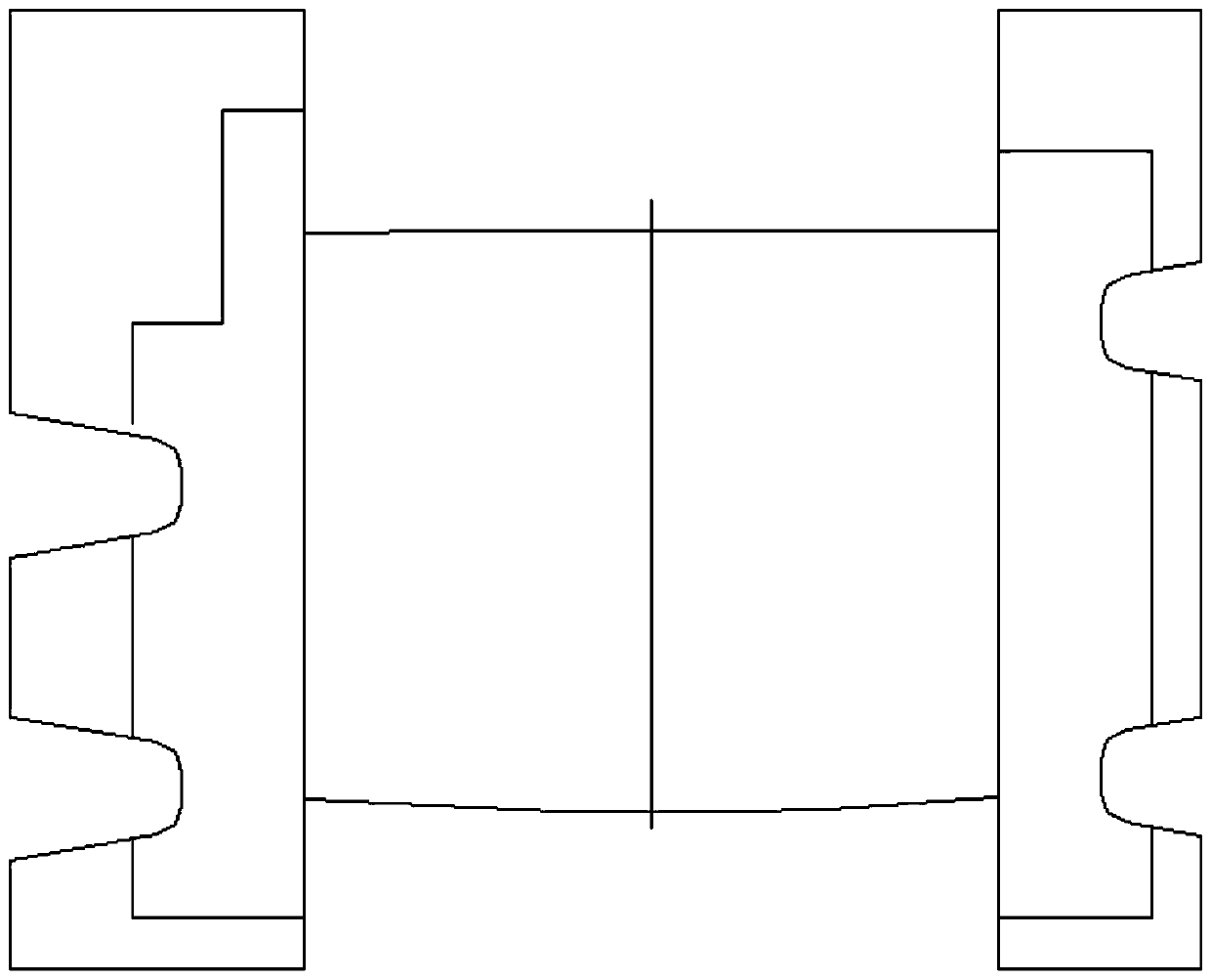
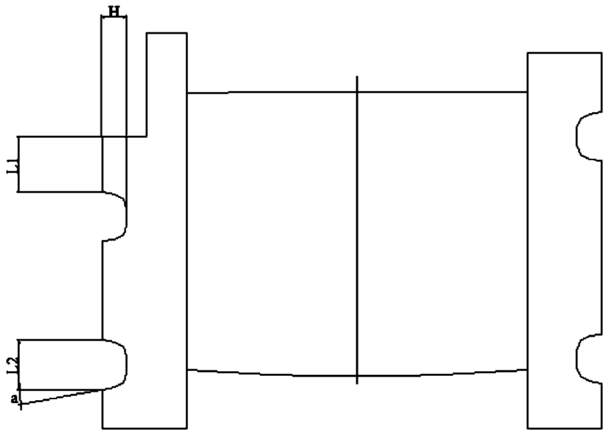
[0019] Specific implementation mode one: refer to figure 1 To illustrate this embodiment, this embodiment provides a method for assembling and welding a half-circle of a clapboard and cascade of a steam turbine with its own crown, and the method is realized through the following steps:

[0020] Step 1: Determine the required number N of guide vanes according to the size of the half-turn of the cascade and the size of a single guide vane, where N is a positive integer;

[0021] Step 2: Put the steam outlet side of the N guide vanes facing up in step 1, and place them on the special tooling for installing and welding the diaphragm static blade cascade in turn, and check that the dimensions of the diaphragm static blade cascade composed of the arranged guide vanes are correct. Cover the pressure ring and press it tightly;

[0022] Step 3: Use bolts to fasten one side of the diaphragm static blade cascade composed of guide vanes in step 2, and respectively place two Mark the pos...

specific Embodiment approach 2

[0030] Specific implementation mode two: refer to figure 1 Describe this embodiment, this embodiment is to further limit the step six described in the first specific embodiment, in this embodiment, in the step six, two Welding groove, the distance between the welding groove on both sides of the inner belt of the diaphragm static cascade and the finished surface is about 10mm, and the welding on both sides of the outer circumference of the diaphragm static blade cascade The distance between the bevel and the finished surface is about 10mm. Other compositions and connection methods are the same as those in Embodiment 1.

specific Embodiment approach 3

[0031] Specific implementation mode three: refer to figure 1 Describe this embodiment, this embodiment is to further limit the step six described in the second specific embodiment, in this embodiment, the welding groove width (distance from precision Processing surface) is 10mm. Other compositions and connection methods are the same as those in the second embodiment.


PUM

PropertyMeasurementUnit
widthaaaaaaaaaa

Abstract

The invention relates to a semi-circle assembling and welding method for shroud partition plate blade grids of a steam turbine, belongs to the technical field of stationary blade grid manufacturing, and aims to solve the problems of poor size precision in the radius direction, inconsistent upper and lower semi-contraction amounts, large welding amount and poor weld joint quality after the shroud partition plate blade grids with shroud structures are welded in the prior art. According to the semi-circle assembling and welding method for the shroud partition plate blade grids of the steam turbine, guide blades are arranged on a special assembling and welding tool for the partition plate blade grids with the steam outlet sides of the guide blades upwards, covering with compression rings is carried out after each size is checked to be qualified, and tightening on one side is carried out by using bolts; and spot welding fixing is carried out at the position, avoiding the positions of innerand outer circle welding grooves, on the joint surfaces of two adjacent guide blades by adopting a manual argon tungsten-arc welding self-fluxing mode, welding reinforcing is conducted through manualshielded metal arc welding, then turning to a vertical lathe procedure is carried out to complete machining of the welding grooves in the static blade grids, and then preheating, welding and stress relief heat treatment work is conducted on the static blade grids. The semi-circle assembling and welding method is mainly used for manufacturing the semi-circle structure partition plate blade grids.

Description

technical field [0001] The invention belongs to the technical field of diaphragm static blade cascade manufacturing, and in particular relates to a half-circle assembly and welding method of a diaphragm blade cascade with a crown attached to a steam turbine. Background technique [0002] In the ultra-supercritical steam turbine unit, the medium-pressure first stage such as CCH03.1201Z, and the low-pressure first-stage diaphragm static blade cascade such as CCH03.1401Z / CCH03.1501Z are self-contained crown structures. Assembly welding is carried out between the inner and outer rings, and the design requires U-shaped grooves to be used for welding connection between adjacent guide vanes. Due to the large number of diaphragm guide vanes, the number of welds is also large (the number of welds is about The number of blades is about 2 times), the welding cycle is also long, and it is difficult to ensure that the welding quality of each weld between the guide vane and the guide vane...

Claims


Application Information

Patent Timeline
Patent Type & Authority Applications(China)
IPC IPC(8): B23K9/167B23K9/23B23K9/235B23K9/32
CPCB23K9/167B23K9/23B23K9/235B23K9/32
Inventor 王广成胡宝成马春光张仁军王传伟
Owner HARBIN TURBINE
Learn More