
Light assembly type steel structure composite floor slab and implementation method thereof

A technology for combining floors and steel structures, applied to floors, floors, building components, etc., can solve the problems of insufficient sound insulation and seismic performance, heavy weight, and heavy wet work, and achieve easy modular manufacturing and production, and easy The effect of transportation and increasing net height

Pending Publication Date: 2020-08-18
河南省第二建设集团有限公司 +1
View PDF0 Cites 3 Cited by
  • Summary
  • Abstract
  • Description
  • Claims
  • Application Information

AI Technical Summary

Problems solved by technology

[0006] In view of the above situation, in order to overcome the defects of the prior art, the present invention provides a light-duty assembled steel structure composite floor and its implementation method, which solves the problems of large wet work volume, heavy weight, thermal insulation performance, sound insulation performance and seismic performance of the existing steel structure floor. Insufficient problem

Method used


Image

  • Light assembly type steel structure composite floor slab and implementation method thereof
  • Light assembly type steel structure composite floor slab and implementation method thereof
  • Light assembly type steel structure composite floor slab and implementation method thereof

Examples


Embodiment 1

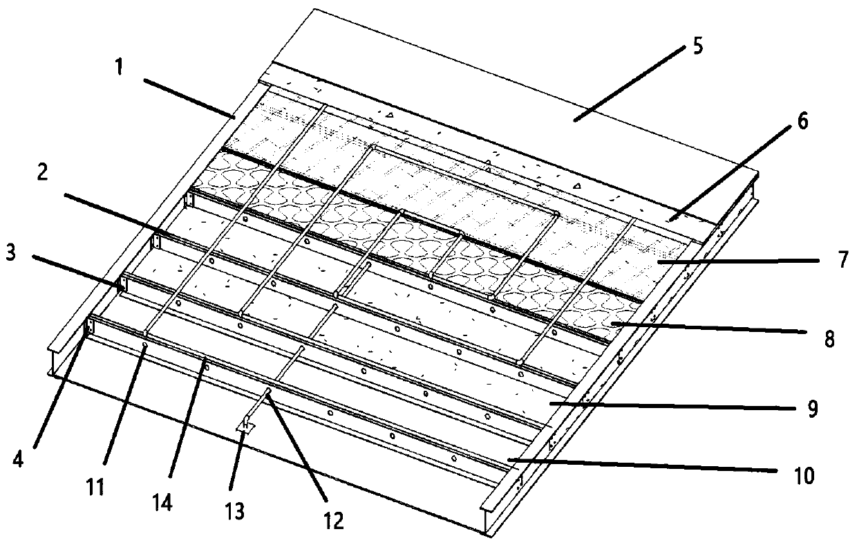
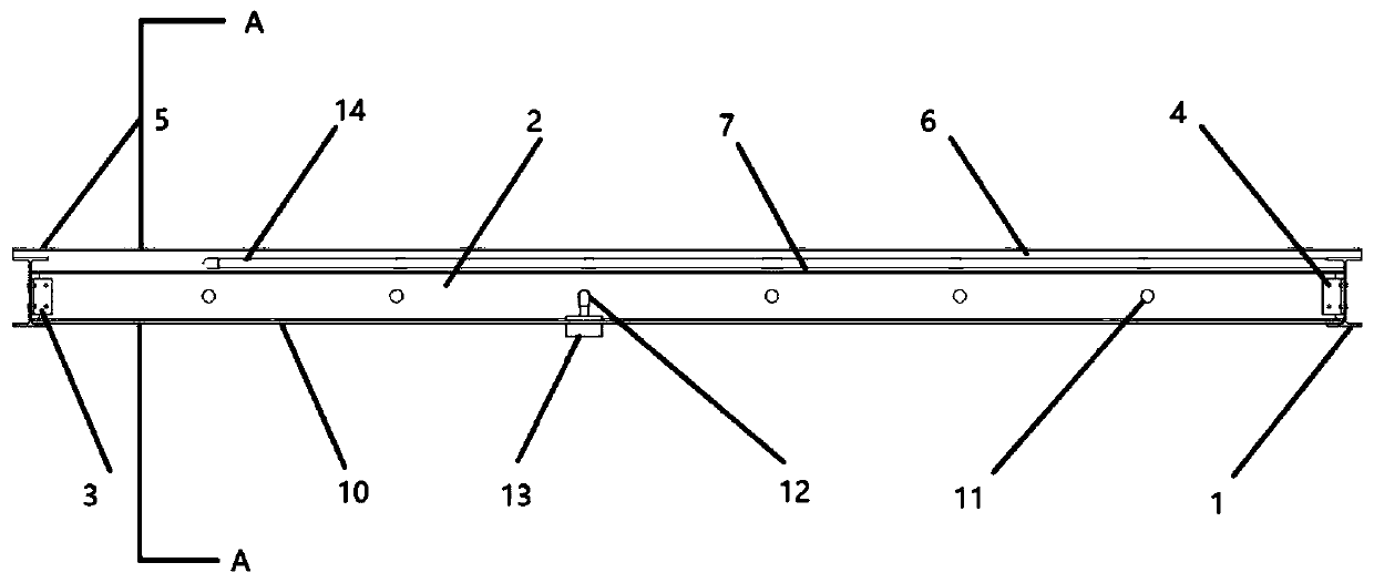
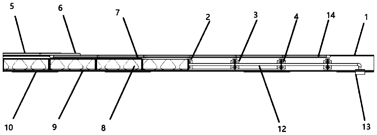
[0040] Embodiment one: by Figure 1 to Figure 6It is given that the light-weight assembled steel structure composite floor used for the assembled steel structure building includes a steel frame, a pipeline 14 and a lightweight concrete layer 6, the steel frame includes a steel beam 1 and a plurality of supporting frames 2, and the supporting frames 2 As the load-bearing skeleton of the composite floor, it plays a supporting role. The bottom surface of each support skeleton 2 is laid with a support plate 9 and the upper surface is laid with a waterproof membrane 7 to form a cavity inside the steel frame. The use of the support plate 9 has the functions of heat preservation and flame retardancy. The board can improve the flame retardancy, heat preservation and waterproof performance of the floor while playing a supporting role. The cavity is filled with a heat insulation and sound insulation layer 8, and the waterproof membrane 7 plays a role in preventing the heat insulation and...

Embodiment 2

[0042] Embodiment 2: On the basis of Embodiment 1, a floor heating pipeline 14 and a lightweight concrete layer 6 are arranged between the waterproof membrane 7 and the ground decoration layer 5. The specific method is: first lay the floor heating pipeline 14, and then pour lightweight concrete , forming a lightweight concrete layer 6 covering the floor heating pipeline 14, the support plate 9 and the heat insulation and sound insulation layer 8 together play the role of supporting formwork for pouring the lightweight concrete layer, and form a horizontal structure together with the cast-in-place lightweight concrete. The anti-instability ability of the support frame 2 is improved, and the waterproof membrane 7 plays a role in preventing the cast-in-place lightweight concrete from eroding the thermal insulation layer 8 .

Embodiment 3

[0043] Embodiment three: on the basis of embodiment two, the position where the waterproof membrane 7 and the beam web are handed over is turned up to form a waterproof structure, which effectively prevents moisture from penetrating downward into the thermal insulation layer 8. Each of the supports The skeleton 2 includes two C-shaped steels arranged with their backs. The flange of the C-shaped steel on which the waterproof membrane 7 is laid is the upper limb flange, and the flange on which the support plate 9 is laid is the lower limb flange, and the width of the upper limb flange is smaller than that of the lower limb flange. Width, each support plate is placed on two opposite C-shaped steel lower limb flanges by laying.

[0044] On the basis of the above-mentioned embodiments, when each support plate 9 is placed on the C-shaped steel, the two can be fixed by gluing, and the glue is applied first, and then placed to form a more effective connection.

[0045] On the basis of...


PUM


Abstract

The invention relates to the technical field of steel structure composite floor slabs, and particularly relates to a light assembly type steel structure composite floor slab and an implementation method thereof. An existing steel structure floor slab is large in field wet operation amount, large in weight and insufficient in heat preservation performance, sound insulation performance and anti-seismic performance. The light assembly type steel structure composite floor slab for an assembly type steel structure building comprises a steel frame, pipelines and a light concrete layer. The steel frame comprises a steel beam and a plurality of supporting frameworks, wherein a supporting plate is laid on the lower bottom face of the steel frame, a waterproof film is laid on the upper top face of the steel frame, and a cavity is formed in the steel frame; the cavity is filled with a heat preservation and sound insulation layer; a decoration layer is laid on the surface of the composite floor slab; pipeline holes allowing the equipment pipelines to penetrate through are reserved in webs of the supporting frameworks; and the equipment pipelines are connected with a junction box. The wet operation amount is reduced, the weight of the floor slab is reduced, meanwhile, good heat preservation, sound insulation and flame retardance are achieved, and good development prospects are achieved in the technical field of steel structure composite floor slabs.

Description

technical field [0001] The invention relates to the technical field of steel structure floor slabs for building construction, in particular to a light-duty assembled steel structure composite floor slab and an implementation method thereof. Background technique [0002] The construction industry is the pillar industry of the national economy. In recent years, my country has vigorously advocated the industrialization of construction. The action plan for prefabricated buildings clearly stated that the proportion of prefabricated buildings in the country accounted for more than 15% of new buildings, and the key promotion areas reached more than 20%. In July 2019, the Ministry of Housing and Urban-Rural Development approved a number of provinces to accelerate the construction of steel structure prefabricated houses as a focus to carry out pilot work, promote the advantages of building production suitable for factory production, and adapt to the housing industry as a residential ...

Claims


Application Information

Patent Timeline
Patent Type & Authority Applications(China)
IPC IPC(8): E04B5/17E04B5/29E04B5/48E04B1/82E04B1/76E04B1/94E04B1/66
CPCE04B1/665E04B1/7608E04B1/8227E04B1/942E04B5/17E04B5/29E04B5/48
Inventor 王庆伟陈东兆李亚克苏群山张振魁段常智
Owner 河南省第二建设集团有限公司
Learn More