Floating type wave energy power generation equipment

A technology for power generation equipment and wave energy, applied in the field of floating wave energy power generation equipment, can solve the problems of limited large-scale application, difficulty and cost increase of pile foundation construction, normal use of ebb and flow, etc., and achieves compact structure, simple structure, The effect of low manufacturing cost

Inactive Publication Date: 2020-08-18
HANGZHOU HUGEWAVE ENERGY TECH CO LTD
View PDF11 Cites 4 Cited by
  • Summary
  • Abstract
  • Description
  • Claims
  • Application Information

AI Technical Summary

Problems solved by technology

This kind of fixed structure is doomed to be used only in offshore areas. As the depth of seawater increases, the difficulty and cost of building pile foundations will increase significantly, which limits its large-scale application.
In addition, even if the structure is applied in the sea, in the case of a large tidal range, the ebb and flow of tides will affect its normal use

Method used


Image

  • Floating type wave energy power generation equipment
  • Floating type wave energy power generation equipment
  • Floating type wave energy power generation equipment

Examples


Embodiment 1

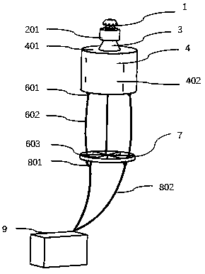
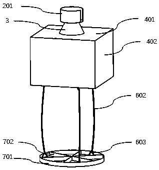
[0039] A floating wave energy power generation device disclosed in this embodiment includes a floating body 4 and an air turbine and generator system 1 arranged on the floating body 4 .

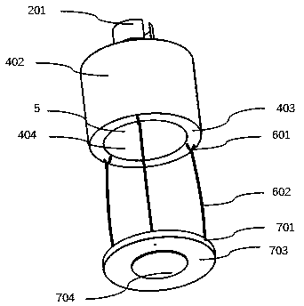
[0040] Wherein, the floating body 4 is a ring structure, and the ring structure is a closed ring, such as Figure 2A , image 3 As shown, the middle part of its closed ring forms a gas-liquid chamber 5, the upper end of the gas-liquid chamber 5 is covered by the upper cover plate 401 of the floating body, the lower end of the gas-liquid chamber 5 is open, and liquid (sea water) enters the air through the lower end opening. Oscillatory fluctuations are carried out in the liquid cavity 5 and in the gas-liquid cavity.

[0041] Wherein, the upper end of the above-mentioned gas-liquid chamber 5 is provided with at least one vent 502 and is configured to form a gas chamber 501 between the liquid surface in the gas-liquid chamber 5 and the top of the gas-liquid chamber. Changes due to fluctuations...

Embodiment 2

[0061] Such as Figure 5A , Figure 5B As shown, on the basis of the first embodiment, when the diameter of the floating body 4 is relatively large, the interior of the gas-liquid chamber 5 can be divided into multiple independent gas-liquid chambers by the partition plate 501 . In this embodiment, the gas-liquid chamber 5 is divided into three gas-liquid chambers. Then, a vent 502 is arranged on the top of each gas-distributing liquid chamber, and a set of air turbine and generator system 1 is installed at the position of each vent 502 .

[0062] The purpose of such setting is to improve the utilization rate of wave energy and improve the power generation efficiency of floating wave energy.

Embodiment 3

[0064] A kind of floating type wave energy generation device disclosed in this embodiment, such as Figure 2A-Figure 2C As shown, a damping structure 7 is also included, the damping structure 7 is arranged under the floating body 4 , and a connection device is provided between the damping structure 7 and the lower part of the floating body 4 .

[0065] Among them, a preferred damping structure 7, such as Figure 2A-Figure 2C As shown, it includes a damping bottom plate 703 , a damping side plate 701 arranged around the damping bottom plate 703 , and several damping reinforcement plates 702 respectively connected to the damping bottom plate 703 and the damping side plate 701 . The damping bottom plate 702 and the damping side plate 701 form a flat barrel structure, and the function of the damping reinforcement plate 702 is to make the entire damping structure stronger.

[0066] Among them, a preferred connection device, such as Figure 2C , Figure 5A As shown, the connectin...


PUM


Abstract

The invention relates to the technical field of ocean renewable energy utilization, and particularly discloses floating type wave energy power generation equipment. The equipment at least comprises afloating body, an air turbine and a power generator, wherein a gas-liquid cavity is formed in the middle of the floating body, the lower end of the gas-liquid cavity is open, at least one air vent isformed in the upper end of the gas-liquid cavity, and a gas cavity is formed between the liquid level in the gas-liquid cavity and the top of the gas-liquid cavity. According to the floating type wavepower generation equipment, the structure is simple, the production and manufacturing cost is low, and the gas-liquid cavity is formed in the middle of the floating body, so that the structure is compact, and the space utilization rate is high; and the application range is not limited by deep sea and offshore area, and meanwhile, the influence of tide rising and tide falling is avoided, so that the application range is wide, large-scale industrial production, manufacturing and application are facilitated, and the equipment has great significance in utilization of renewable resources such as wave energy for countries with rich marine resources.

Description

technical field [0001] The invention relates to the technical field of marine renewable energy utilization, in particular to a floating wave energy power generation device. Background technique [0002] Ocean buoys are important carriers for carrying ocean observation and communication equipment. Because it is necessary to have sufficient power supply for ocean observation and communication, the current way to power ocean buoys is to use solar energy and wind energy to power batteries, but because the energy density of solar energy and wind energy is low and unstable, so For functional buoys with large power consumption, solar energy and wind energy often cannot meet their needs. [0003] Wave energy is a widely distributed, high energy density (more than 300 times that of solar energy and more than 80 times that of wind energy), and very stable renewable energy (an average annual utilization time of more than 5,000 hours). Therefore, it is very valuable and significant to...

Claims


Application Information

Patent Timeline
Patent Type & Authority Applications(China)
IPC IPC(8): F03B13/24F03B13/14F03B15/00F03B15/02
CPCF03B13/24F03B13/14F03B13/142F03B15/00F03B15/02F05B2220/706Y02E10/30
Inventor 范景润
Owner HANGZHOU HUGEWAVE ENERGY TECH CO LTD
Why Eureka
Try Eureka