Control method of high-order LCLCL direct-current converter

A technology of a DC converter and a control method, which is applied in the conversion of DC power input to DC power output, control/regulation systems, high-efficiency power electronic conversion, etc., can solve the problem that power converters are not suitable for LCLCL high-order systems.

Active Publication Date: 2020-08-18
HARBIN INST OF TECH
View PDF11 Cites 4 Cited by
  • Summary
  • Abstract
  • Description
  • Claims
  • Application Information

AI Technical Summary

Problems solved by technology

[0007] Aiming at the problem that the existing power converter control method is not applicable to the LCLCL high-order system, the present invention provides a control method for the high-order LCLCL DC converter

Method used


Image

  • Control method of high-order LCLCL direct-current converter
  • Control method of high-order LCLCL direct-current converter
  • Control method of high-order LCLCL direct-current converter

Examples


specific Embodiment approach 1

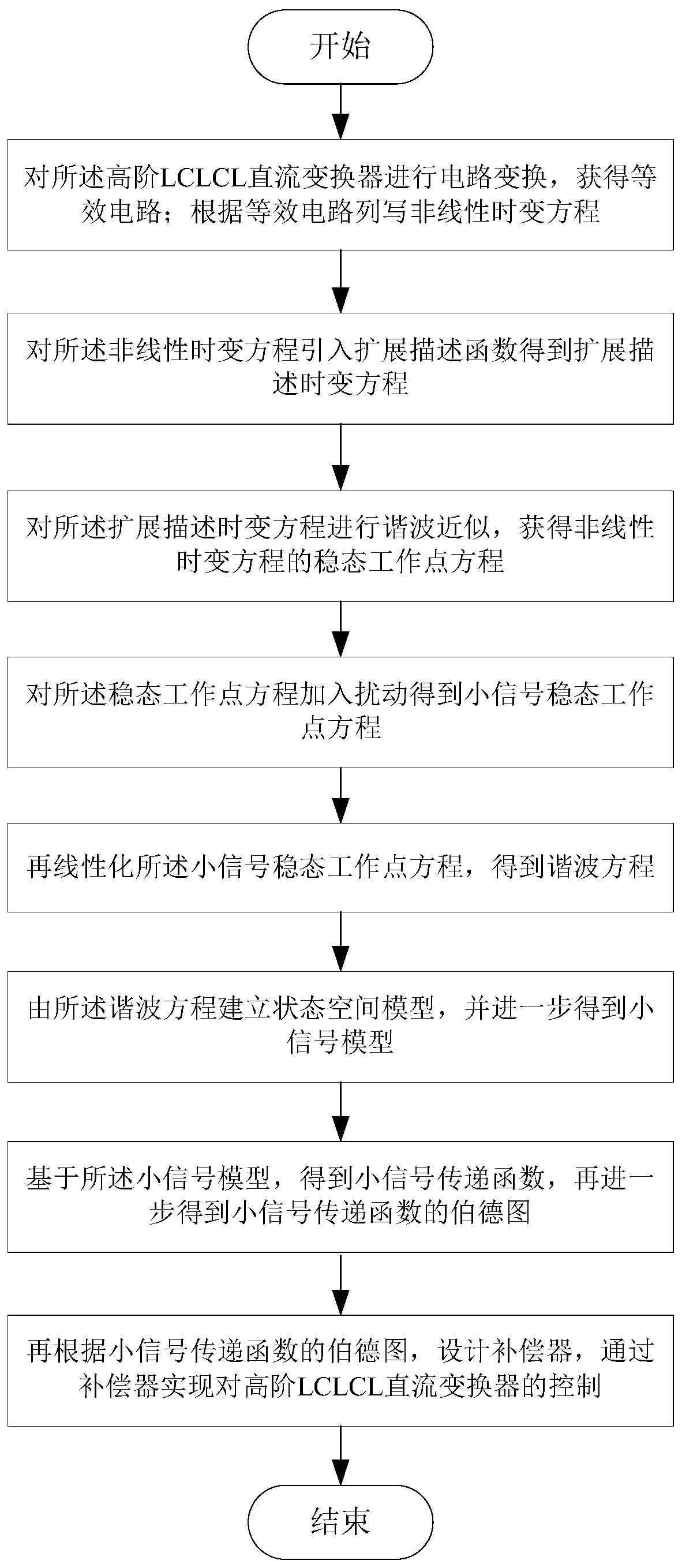
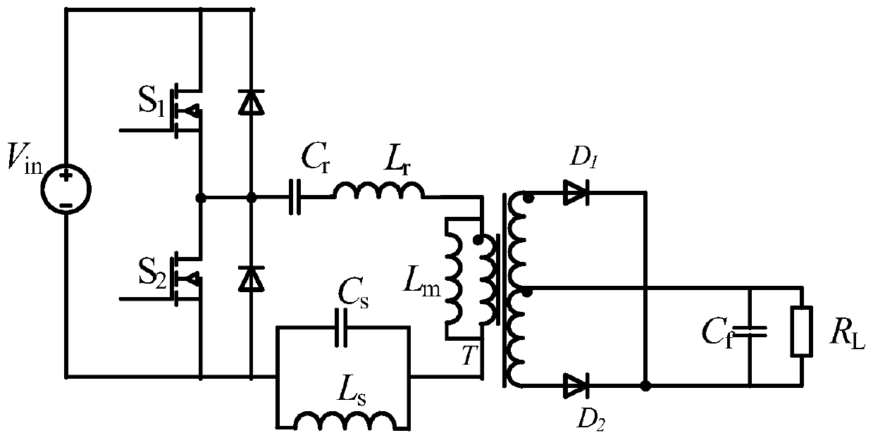
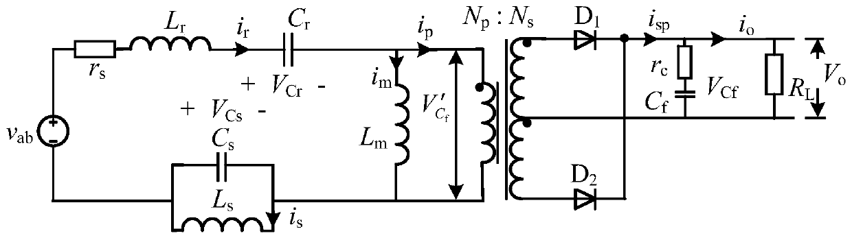
[0037] Specific implementation mode 1. Combination figure 1 As shown, the present invention provides a control method of a high-order LCLCL DC converter, and the high-order LCLCL DC converter includes a switching tube S 1 , switch tube S 2 , Resonant capacitance C r , Resonant inductance L r , transformer T, band stop filter inductor L s , Band stop filter capacitor C s , Diode D 1 , Diode D 2 and output capacitor C f ,

[0038] Band stop filter inductor L s and bandstop filter capacitor C s are connected in parallel to form a band-stop filter;

[0039] Switch tube S 1 The drain is connected to the power supply V in positive pole of the switch tube S 1 The source is connected to the switch S 2 The drain of the switch tube S 2 The source is connected to the power supply V in The negative pole of the resonant capacitor C r , Resonant inductance L r , the primary side of the transformer T and the band-stop filter are connected in series in the switch tube S 2 b...

specific Embodiment

[0168] In order to verify the feasibility of selecting the topology and parameter design of the present invention, a prototype with the following indicators was built

[0169] Rated input voltage: 400V;

[0170] Rated power: 400W;

[0171] Series resonant frequency: 1MHz (fundamental wave), 3MHz (third harmonic);

[0172] Parallel resonance frequency: 2MHz;

[0173] Efficiency: higher than 95%;

[0174] Output voltage: 24V;

[0175] Output voltage ripple: less than 200mV;

[0176] The chip type and parameters of the DC converter selected by the prototype are shown in Table 1.

[0177] Table 1

[0178]

[0179] According to the parameters in the above table, the resonance parameters, load parameters, and parasitic parameters are substituted into the model, and the following can be obtained: Figure 5 The transfer function of the pole-zero distribution shown.

[0180] Going one step further, the bode image before compensation is obtained as shown in Figure 6 shown; ...


PUM


Abstract

The invention discloses a control method of a high-order LCLCL direct-current converter, belongs to the technical field of direct-current converter control, and aims to solve the problem that an existing control method of a power converter is not suitable for an LCLCL high-order system. The method comprises the steps of performing circuit transformation on the high-order LCLCL direct-current converter to obtain an equivalent circuit; listing a nonlinear time-varying equation according to the equivalent circuit; introducing an extended description function into the nonlinear time-varying equation to obtain an extended description time-varying equation; performing harmonic approximation on the extended description time-varying equation to obtain a steady-state working point equation of the nonlinear time-varying equation; adding disturbance to the steady-state working point equation to obtain a small-signal steady-state working point equation; linearizing the small signal steady-state working point equation to obtain a harmonic equation; and establishing a state space model according to the harmonic equation, and further obtaining a small signal model. According to the invention, theconverter can obtain satisfactory dynamic characteristics under different input voltage and load conditions.

Description

technical field [0001] The invention relates to a control method of a high-order LCLCL DC converter, and belongs to the technical field of DC converter control. Background technique [0002] In the field of DC / DC power converters, the power density and efficiency of the power supply are two important indicators for evaluating its performance. Increasing the switching frequency of the converter can improve the efficiency of the switching power supply, but the increase in the switching frequency will lead to a significant increase in switching loss, and its efficiency will also decrease significantly with the increase in frequency. Therefore, high-frequency DC / DC power converters are more The LC resonance method is used to realize the working state of soft switching, thereby eliminating switching loss and improving the working efficiency of the power converter. [0003] In the existing LLC resonant converter within a certain frequency range, by changing the switching frequenc...

Claims


Application Information

Patent Timeline
Patent Type & Authority Applications(China)
IPC IPC(8): H02M3/335H02M1/088H02M1/14H02M1/36
CPCH02M3/33569H02M1/088H02M1/083H02M1/14H02M1/36H02M1/0058Y02B70/10
Inventor 戴明聪张相军管乐诗王懿杰徐殿国袁佳音孙宇豪井嘉晨
Owner HARBIN INST OF TECH
Why Eureka
Try Eureka