Prefabricated wall, building and construction component management system thereof

A building and prefabricated technology, applied in the field of solar energy, can solve the problems of not being able to fully ensure the beauty of the building, reduce the assembly efficiency of the building structure, and the low utilization rate of solar thermal efficiency, so as to improve the reasonable utilization efficiency, reduce the dead zone of refrigerant flow, Maintain the overall aesthetic effect

Active Publication Date: 2020-08-21
QINGJIAN GRP CO LTD
View PDF8 Cites 9 Cited by
  • Summary
  • Abstract
  • Description
  • Claims
  • Application Information

AI Technical Summary

Problems solved by technology

However, in the current practical engineering application, on the one hand, the aesthetics of the building cannot be fully guaranteed, and at the same time, the space occupancy rate of the wall may be too large, which reduces the assembly efficiency of the building structure; on the other hand, there is a problem of low utilization rate of solar thermal efficiency.
[0006] In view of the above analysis, there are the following technical problems in the prior art: the solar energy utilization efficiency of the integrated building wall is low, the space occupancy rate of the wall may be too large, and the assembly efficiency of the building structure is reduced, so it needs to be improved

Method used


Image

  • Prefabricated wall, building and construction component management system thereof
  • Prefabricated wall, building and construction component management system thereof
  • Prefabricated wall, building and construction component management system thereof

Examples


Embodiment Construction

[0048] The present application will be further described below in conjunction with the accompanying drawings and specific embodiments.

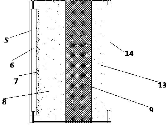
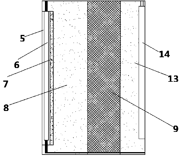
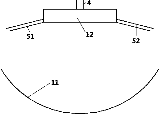
[0049] Figures 1-1 and 1-2 show two solar prefabricated building walls. As shown in Figure 1-1, the wall includes a transparent plate 5, a preheating pipe 6, an insulating layer 7, an outer load-bearing wall 8, Insulation layer 9, inner bearing wall 13, ventilation part 14; said transparent plate 5, preheating pipe 6, heat insulating layer 7 are arranged on the outer surface of outer bearing wall 8, transparent plate 5 is arranged on the outside of preheating pipe 6, heat insulating layer 7 Set on the inner side of the preheating pipe 6, the insulation layer 9 is installed between the outer bearing wall 8 and the inner bearing wall 13; the ventilation part 14 is arranged on the inner surface of the inner bearing wall 13; the upper entrance of the ventilation part 14 Connect the solar heat collector 1, the preheating pipe 6 extends from the up...


PUM

PropertyMeasurementUnit
lengthaaaaaaaaaa
lengthaaaaaaaaaa
lengthaaaaaaaaaa

Abstract

The invention provides a prefabricated wall, a building and a construction component management system thereof. The prefabricated wall includes a transparent board, a preheating tube, a heat insulating layer, an outer bearing wall, an thermal insulation layer, an inner bearing wall, and a ventilation component; the transparent board, the preheating tube and the heat insulating layer are arranged on the outer surface of the outer bearing wall, the transparent board is arranged on the outside of the preheating pipe, the heat insulating layer is arranged on the inner side of the preheating pipe,and the thermal insulation layer is installed between the outer bearing wall and the inner bearing wall; the ventilation component is arranged on the inner surface of the inner bearing wall; the upperentrance of the ventilation component is connected to a solar collector; the preheating tube enters the wall from the upper part of the wall; the lower part of the wall is a closed structure; the preheating tube is provided with branches, and the branch entrance extends into the room inside the wall; and the lower entrance is provided with a fan. The invention provides a new solar air-conditioning building wall located at the bottom of the building, which achieves the air conditioning effect and improves the utilization degree and utilization efficiency of solar energy.

Description

technical field [0001] The invention belongs to the technical field of solar energy, and in particular relates to a solar air-conditioned building wall and a system thereof. Background technique [0002] With the continuous development of the economy and the massive consumption of energy, energy conservation has become a topic of global concern. Renewable energy such as solar energy, wind energy, and geothermal energy, and the utilization of industrial waste heat and waste heat have become the focus of research and development in various countries. However, these energy sources have Due to the characteristics of discontinuity and instability, the research on energy storage technology is particularly important. Heat storage technology is one of energy storage technologies, and an important part of heat storage technology is the design of phase change heat storage heat exchanger. The common phase change regenerative heat exchanger consists of two tubes set together, and the c...

Claims


Application Information

Patent Timeline
Patent Type & Authority Applications(China)
IPC IPC(8): E04B2/00E04B1/74E04C2/52E04C2/284F24D15/00F24S10/70F24S23/70G06F30/13G06Q50/08C04B28/04
CPCE04B2/00F24D15/00F24D2200/14F24S10/70F24S23/70F24S2010/71Y02E10/44
Inventor 李翠翠张同波付长春叶林其他发明人请求不公开姓名
Owner QINGJIAN GRP CO LTD
Why Eureka
Try Eureka