
Power transformer fault diagnosis method and power transformer fault diagnosis device

A technology for power transformers and transformer faults, applied in transformer testing, measuring devices, and measuring electrical variables, etc., can solve problems such as poor pertinence, inaccurate fault identification, and unclear influence weights of transformers

Active Publication Date: 2020-08-21
HUNAN UNIV OF ARTS & SCI
View PDF7 Cites 10 Cited by
  • Summary
  • Abstract
  • Description
  • Claims
  • Application Information

AI Technical Summary

Problems solved by technology

However, the existing power transformer fault diagnosis methods and power transformer fault diagnosis devices are inaccurate in fault identification, fault diagnosis models are not accurate, and the possible impact weights of various operating parameters on transformer faults are not clear; at the same time, the analysis of transformer data Inaccurate, poorly targeted
[0003] In summary, the existing problems in the prior art are: the existing power transformer fault diagnosis method and power transformer fault diagnosis device are inaccurate in fault identification, the fault diagnosis model is inaccurate, and the possible influence weight of each operating parameter on the occurrence of transformer faults etc. are not clear; at the same time, the analysis of transformer data is inaccurate and poorly targeted
[0004] The significance of solving the above problems and defects is: when a power transformer fails, it will lead to power supply interruption, which will affect the reliability of power users. If it is an industrial user, it will affect the continuity of production; if it is serious, the transformer will catch fire and explode. Accidents, resulting in serious equipment damage and casualties

Method used


Image

  • Power transformer fault diagnosis method and power transformer fault diagnosis device
  • Power transformer fault diagnosis method and power transformer fault diagnosis device
  • Power transformer fault diagnosis method and power transformer fault diagnosis device

Examples


Embodiment 1

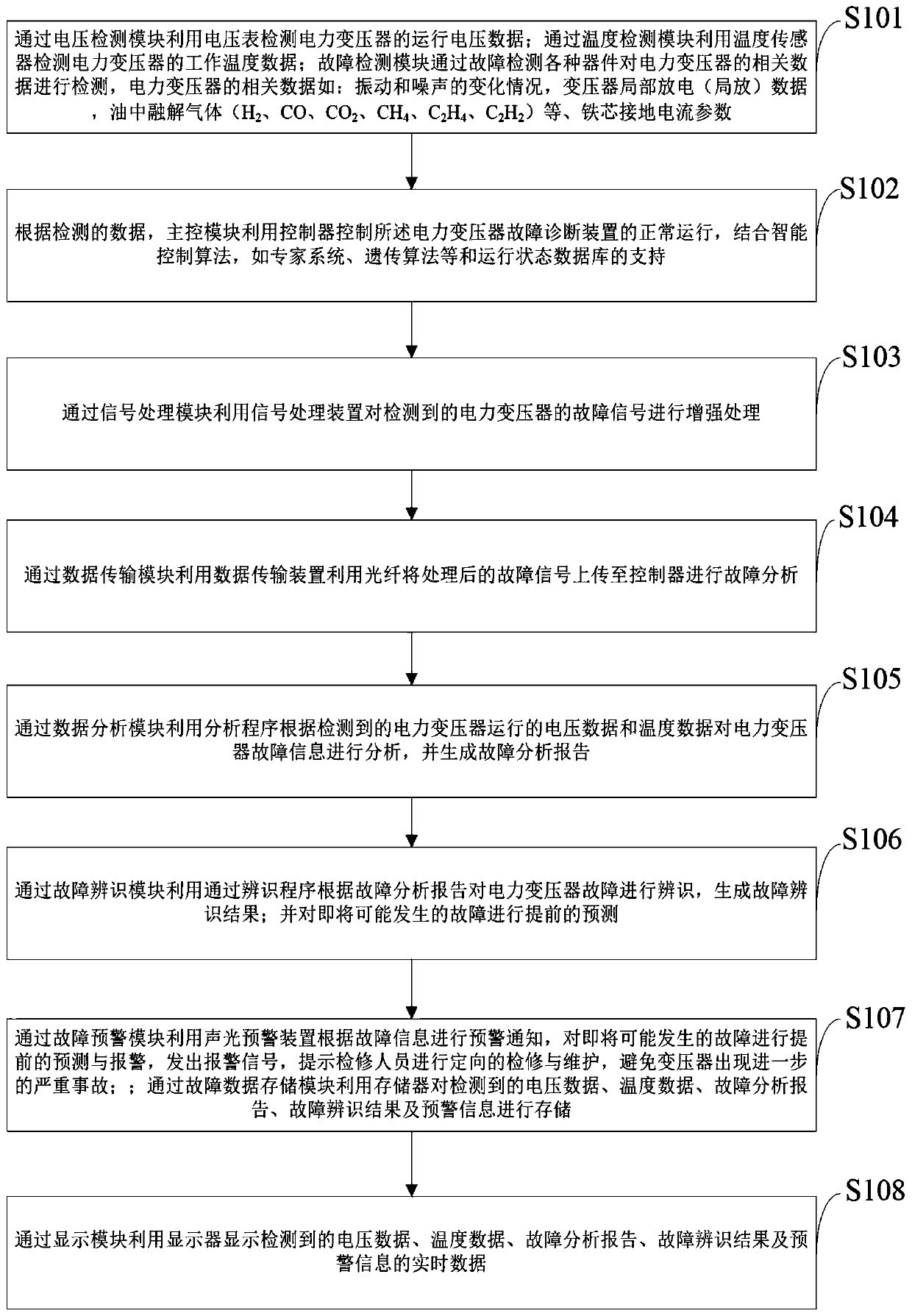
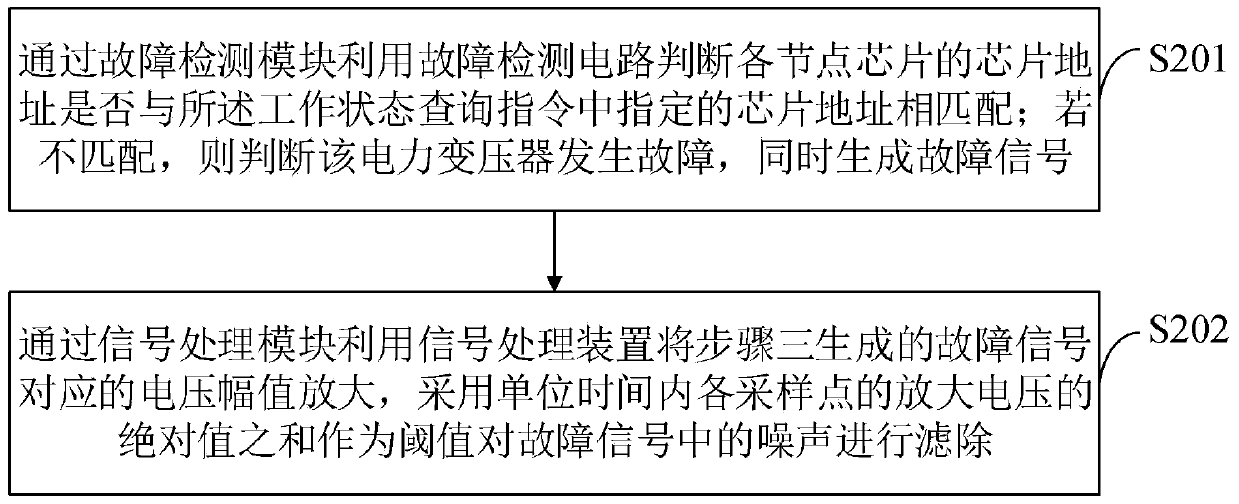
[0103] The power transformer fault diagnosis method provided by the embodiment of the present invention is as follows: figure 1 shown, as a preferred embodiment, as image 3 As shown, the method for detecting and enhancing the relevant parameters of the power transformer provided by the embodiment of the present invention includes:

[0104] S201, the fault detection module uses the fault detection device to determine whether the chip address of each node chip matches the chip address specified in the working state query instruction; if not, it is determined that the power transformer is faulty, and a fault signal is generated simultaneously.

[0105] S202, the signal processing module uses the signal processing device to amplify the voltage amplitude corresponding to the fault signal generated in step 3, and uses the sum of the absolute values ​​of the amplified voltages at each sampling point per unit time as the threshold to filter out the noise in the fault signal .

[01...

Embodiment 2

[0111] The power transformer fault diagnosis method provided by the embodiment of the present invention is as follows: figure 1 shown, as a preferred embodiment, as Figure 4 As shown, the method for analyzing the fault information of the power transformer and generating the fault analysis report according to the detected voltage data, temperature data and relevant operating parameters of the power transformer through the analysis program provided by the embodiment of the present invention includes:

[0112] S301, obtain historical monitoring data of the transformer through monitoring equipment, and obtain real-time fault signal data of the transformer transmitted by the data transmission device.

[0113] S302, the data analysis module utilizes an analysis program to screen the historical monitoring data of the transformer and the effective fault data in the real-time fault signal data of the transformer according to a preset data reduction standard.

[0114] S303, analyze th...

Embodiment 3

[0123] The power transformer fault diagnosis method provided by the embodiment of the present invention is as follows: figure 1 shown, as a preferred embodiment, as Figure 5 As shown, the identification program provided by the embodiment of the present invention identifies the power transformer fault according to the fault analysis report, and the method for generating the fault identification result includes:

[0124] S401, the fault identification module uses the identification program to read in the transformer fault analysis report from the database server, number the transformer fault analysis data types according to the data names, and set them as A, B, C... Type press A 1 ~A n , B 1 ~B m , C 1 ~C k ...to be numbered; set transformer fault type to F, press F for it 1 ~F t number.

[0125] S402 , perform data preprocessing on the data numbered A, B, C . . . obtained in S401 , that is, perform missing value filling and denoising processing on them, and then perfo...


PUM


Abstract

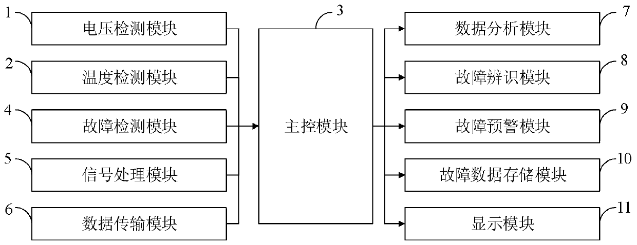
The invention belongs to the technical field of power transformer fault diagnosis, and discloses a power transformer fault diagnosis method and a power transformer fault diagnosis device. The power transformer fault diagnosis device comprises: a voltage detection module, a temperature detection module, a main control module, a fault detection module, a signal processing module, a data transmissionmodule, a data analysis module, a fault identification module, a fault early warning module, a fault data storage module and a display module. More related operation data are added through the faultidentification module, a classifier is reasonably trained according to the influence weight of data on fault identification, related training data can be input according to requirements to adjust parameters and precision of the classifier, and finally the effect of reasonably identifying transformer faults is achieved. And the data analysis module is more targeted, so that the electric power department can effectively manage a distribution transformer according to the transformer data analysis report, and the level of managing the distribution transformer is improved.

Description

technical field [0001] The invention belongs to the technical field of power transformer fault diagnosis, and in particular relates to a power transformer fault diagnosis method and a power transformer fault diagnosis device. Background technique [0002] Transformer is a device that uses the principle of electromagnetic induction to change the AC voltage. The main components are the primary coil, the secondary coil and the iron core (magnetic core). The main functions are: voltage transformation, current transformation, impedance transformation, isolation, voltage regulation (magnetic saturation transformer), etc. According to the purpose, it can be divided into: power transformers and special transformers (electric furnace transformers, rectifier transformers, power frequency test transformers, voltage regulators, mining transformers, audio transformers, intermediate frequency transformers, high frequency transformers, impact transformers, instrument transformers, electron...

Claims


Application Information

Patent Timeline
IPC IPC(8): G01R31/00G01R31/62G01R31/12G01D21/02G06K9/62
CPCG01R31/00G01R31/62G01R31/12G01D21/02G06F18/2135G06F18/2411
Inventor 杨民生李建奇李建英黄世付杨智孙健张家跃黄丽娟
Owner HUNAN UNIV OF ARTS & SCI
Learn More