High-energy electron beam source control system, method and device and part manufacturing method

A high-energy electron beam and control method technology, applied in the field of high-energy electron beam source control system, can solve problems such as accelerated synchronization matching

Inactive Publication Date: 2020-08-21
XIDIAN UNIV
View PDF6 Cites 2 Cited by
  • Summary
  • Abstract
  • Description
  • Claims
  • Application Information

AI Technical Summary

Problems solved by technology

However, there are still problems such as the structural design of the pseudo-spark discharge device, the impedance matching between the nanosecond pulse power supply and the pseudo-spark discharge plasma, the reliable discharge of the pseudo-spark gap under the nanosecond pulse condition, and the synchronous matching between the post-acceleration pulse power supply and the pseudo-spark discharge power supply.

Method used


Image

  • High-energy electron beam source control system, method and device and part manufacturing method
  • High-energy electron beam source control system, method and device and part manufacturing method
  • High-energy electron beam source control system, method and device and part manufacturing method

Examples


Embodiment Construction

[0032] In order to make the object, technical solution and advantages of the present invention more clear, the present invention will be further described in detail below in conjunction with the examples. It should be understood that the specific embodiments described here are only used to explain the present invention, not to limit the present invention.

[0033] Aiming at the problems existing in the prior art, the present invention provides a high-energy electron beam source control system, method, device, and component manufacturing method. The present invention will be described in detail below in conjunction with the accompanying drawings.

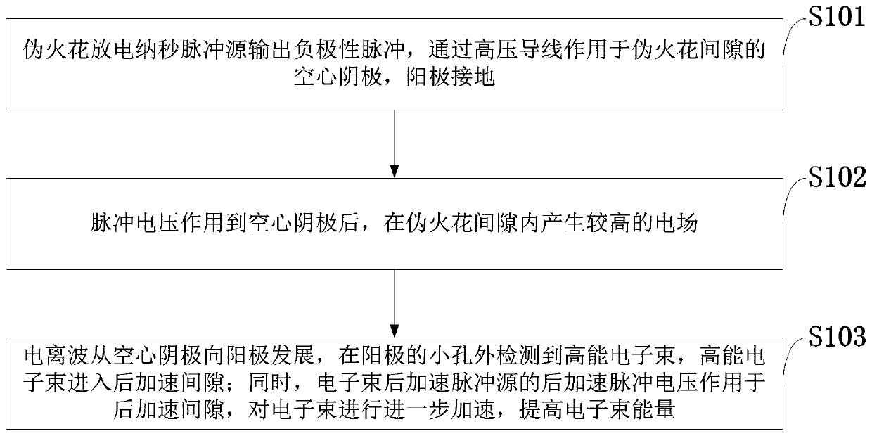
[0034] Such as figure 1 As shown, the high-energy electron beam source control method provided by the present invention comprises the following steps:

[0035] S101: The pseudo-spark discharge nanosecond pulse source outputs a negative polarity pulse, which acts on the hollow cathode of the pseudo-spark gap through a high-voltage wi...


PUM


Abstract

The invention belongs to the technical field of pulse power and terahertz electron beam sources, and discloses a high-energy electron beam source control system, method and device and a part manufacturing method. According to the method, pseudo spark discharge pulses are used for driving pseudo spark gaps to discharge to generate high-energy electron beams; and after the high-energy electron beamsare obtained, an electron beam post-acceleration pulse is used for post-acceleration gap acceleration of the electron beams to improve electron beam energy. The technical scheme comprises a pseudo spark discharge pulse, a pseudo spark discharge gap and an electron beam post-acceleration pulse, wherein the pseudo spark gap is composed of a hollow cathode, an intermediate electrode, an anode, a post-acceleration gap and an insulating shell, a small hole is formed in the center of each electrode, the hole diameter is 1-3 mm and is equal to the gap distance, the thickness of an electrode plate, and the like, the pseudo spark gap forms a sealed cavity, and the air pressure in the cavity is below 100 Pa. According to the invention, high electron beam energy can be obtained under the condition that the pseudo spark discharge gap is small in size.

Description

technical field [0001] The invention belongs to the technical field of pulse power and terahertz electron beam sources, and in particular relates to a high-energy electron beam source control system, method, device, and part manufacturing method. Background technique [0002] At present, in the development process of modern high-tech, laser beam, electron beam, ion beam (referred to as "three beams") technology has made great contributions, and the fields of its role involve material science, metallurgical technology and large-scale Integrated circuits, optoelectronic technology, biotechnology, etc. With the progress of science and technology, especially the rapid development of electronics, aviation, aerospace, bioengineering, medical treatment, automobile industry, etc., higher and higher requirements are put forward for the production process, processing accuracy and performance of materials or parts. Traditional processing methods have been unable to meet the needs of p...

Claims


Application Information

Patent Timeline
Patent Type & Authority Applications(China)
IPC IPC(8): H01J37/302H01J37/04H01J37/06
CPCH01J37/04H01J37/06H01J37/302
Inventor 张佳铁维昊邓伟锋何宏伟付恒魏莹
Owner XIDIAN UNIV
Why Eureka
Try Eureka