
Multifunctional solvent rectification recovery device

A recovery device and a multifunctional technology, which are applied to the recovery of the above-mentioned multifunctional solvent rectification recovery device and the multifunctional solvent rectification recovery device field, can solve the problems of high processing cost, large processing workload, waste of solvent resources, etc. The economic and environmental governance is coordinated and unified, the degree of automation is high, and the effect of solving the emission problem

Pending Publication Date: 2020-08-25
江苏京控装备有限公司
View PDF9 Cites 1 Cited by
  • Summary
  • Abstract
  • Description
  • Claims
  • Application Information

AI Technical Summary

Problems solved by technology

[0002] In the process of industrial production, various solvents are needed, so a large amount of waste solvents will also be produced. Especially in pharmaceutical and chemical enterprises, the products in the production process change rapidly, and the waste solvents produced are complex and diverse, and they are directly treated and discharged. The amount is large, the processing cost is high, and it will cause a waste of solvent resources
[0003] At present, although there are already devices capable of recovering solvents, the existing related devices are generally relatively large in size, require high site space, and have relatively single functions, which cannot be adjusted according to the waste solvents to be processed, making it difficult to solve the problem , The bottleneck of complex types of solvents in the fine chemical industry, the small amount of a single type, and difficulty in recycling

Method used


Image

  • Multifunctional solvent rectification recovery device

Examples


Embodiment Construction

[0021] In order to make the purpose, technical solutions and advantages of the embodiments of the present invention clearer, the following will clearly and completely describe the technical solutions in the embodiments of the present invention in conjunction with the accompanying drawings of the present invention. Obviously, the described embodiments are part of the present invention Examples, not all examples. Based on the embodiments of the present invention, all other embodiments obtained by persons of ordinary skill in the art without making creative efforts belong to the protection scope of the present invention.

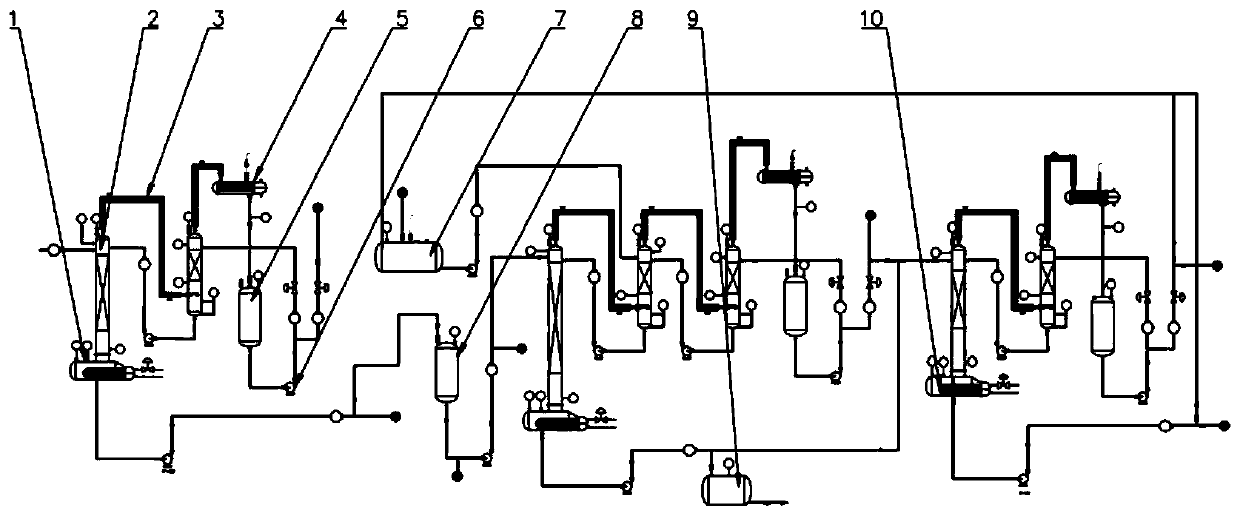
[0022] refer to figure 1 , a multifunctional solvent rectification recovery device, the device includes several stages of solvent rectification recovery mechanism, each stage of solvent rectification recovery mechanism includes a rectification tower 2, a reboiler 1, a condenser 4 and a reflux tank 5, the rectification The inlet end of the distillation tower 2 ...


PUM


Abstract

A multifunctional solvent rectification recovery device comprises multiple stages of solvent rectification recovery mechanisms. Each stage of solvent rectification recovery mechanism comprises a rectifying tower, a reboiler, a condenser and a reflux tank, wherein the inlet end of the rectifying tower is communicated with an input pipeline, the inlet end of the reboiler is communicated with the liquid phase outlet end of the rectifying tower, the liquid phase outlet end of the reboiler is communicated with an output pipeline, the gas phase outlet end of the reboiler is communicated with the inlet end of the rectifying tower, the gas phase outlet end of the rectifying tower is communicated with the inlet end of the condenser, the outlet end of the condenser is communicated with the reflux tank, the reflux tank is communicated with a discharge pipeline, and the discharge pipeline is further connected with a reflux pipeline communicated with the rectifying tower. The input pipeline of thelater-stage solvent rectification recovery mechanism is communicated with the output pipeline of the previous-stage solvent rectification recovery mechanism. The device is reasonable in design and high in automation degree, waste can be turned into wealth, waste solvents generated by medical and chemical enterprises can be rectified, recycled and reused, and coordination and unification of society, economy and environmental governance are achieved.

Description

technical field [0001] The invention relates to the technical field of solvent recovery, in particular to a multifunctional solvent rectification recovery device, and also relates to a recovery method of the multifunctional solvent rectification recovery device. Background technique [0002] In the process of industrial production, various solvents are needed, so a large amount of waste solvents will also be produced. Especially in pharmaceutical and chemical enterprises, the products in the production process change rapidly, and the waste solvents produced are complex and diverse, and they are directly treated and discharged. The amount is large, the processing cost is high, and it will cause a waste of solvent resources. [0003] At present, although there are already devices capable of recovering solvents, the existing related devices are generally relatively large in size, require high site space, and have relatively single functions, which cannot be adjusted according t...

Claims


Application Information

Patent Timeline
IPC IPC(8): B01D3/14
CPCB01D3/146
Inventor 戴春江卢涛曹正球
Owner 江苏京控装备有限公司
Learn More