Multi-stage grinding machine for mechanical equipment production

A technology of mechanical equipment and grinding machines, which is applied in the direction of grinding machine tools, metal processing equipment, and parts of grinding machine tools. It can solve the problems of inconvenient grinding of workpieces and easy mutual influence, and achieves easy maintenance and replacement, large transmission ratio, and stable transmission. Effect

Inactive Publication Date: 2020-08-25
云和县隆盛机械设计工作室
View PDF6 Cites 3 Cited by
  • Summary
  • Abstract
  • Description
  • Claims
  • Application Information

AI Technical Summary

Problems solved by technology

[0003] The Chinese patent with the publication number (CN207139514U) discloses a grinding machine for multi-stage polishing. The patented technology adjusts the height of the grinding device through a hydraulic telescopic rod, and the moving device laterally displaces the grinding device to drive the first polishing disc and the second polishing disc. The disc polishes the polishing piece, the first polishing disc roughly polishes the polishing piece, and the second polishing disc performs fine polishing on the polishing piece, but when the workpiece is polished by the first polishing disc and the second polishing disc, due to the first The polishing disc and the second polishing disc are at the same horizontal position. When rough polishing and fine polishing are performed on the workpiece respectively, the first polishing disc and the second polishing disc are easy to interact with each other, which makes the first polishing disc and the second polishing disc inconvenient. The workpiece is polished, therefore, those skilled in the art provide a kind of multi-stage grinding machine for mechanical equipment production, to solve the problems raised in the above-mentioned background technology

Method used


Image

  • Multi-stage grinding machine for mechanical equipment production
  • Multi-stage grinding machine for mechanical equipment production
  • Multi-stage grinding machine for mechanical equipment production

Examples


Embodiment Construction

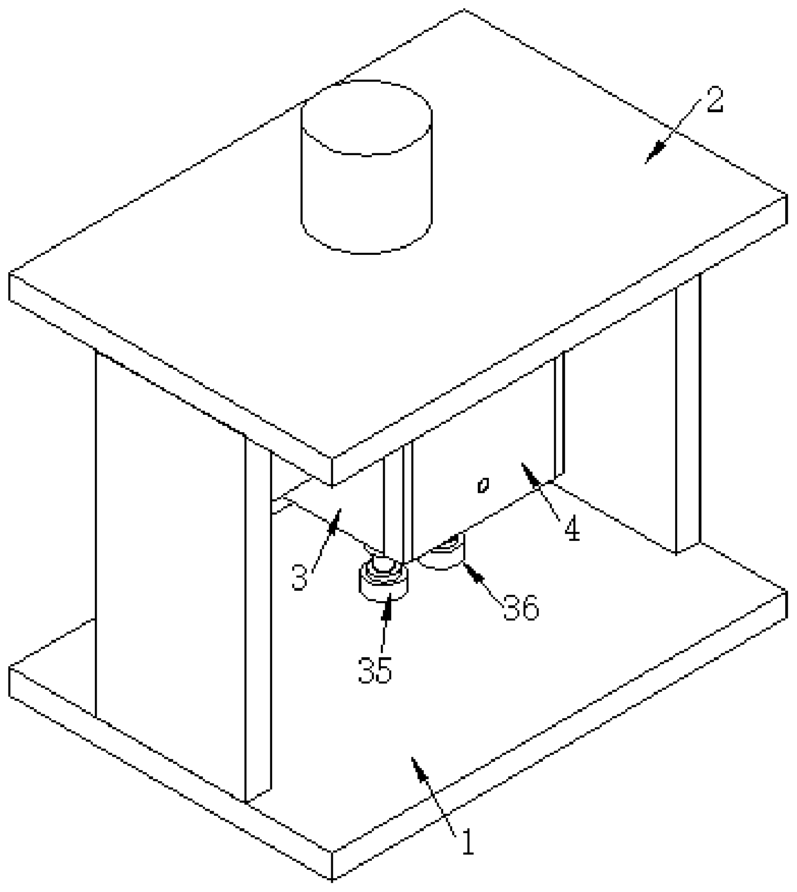
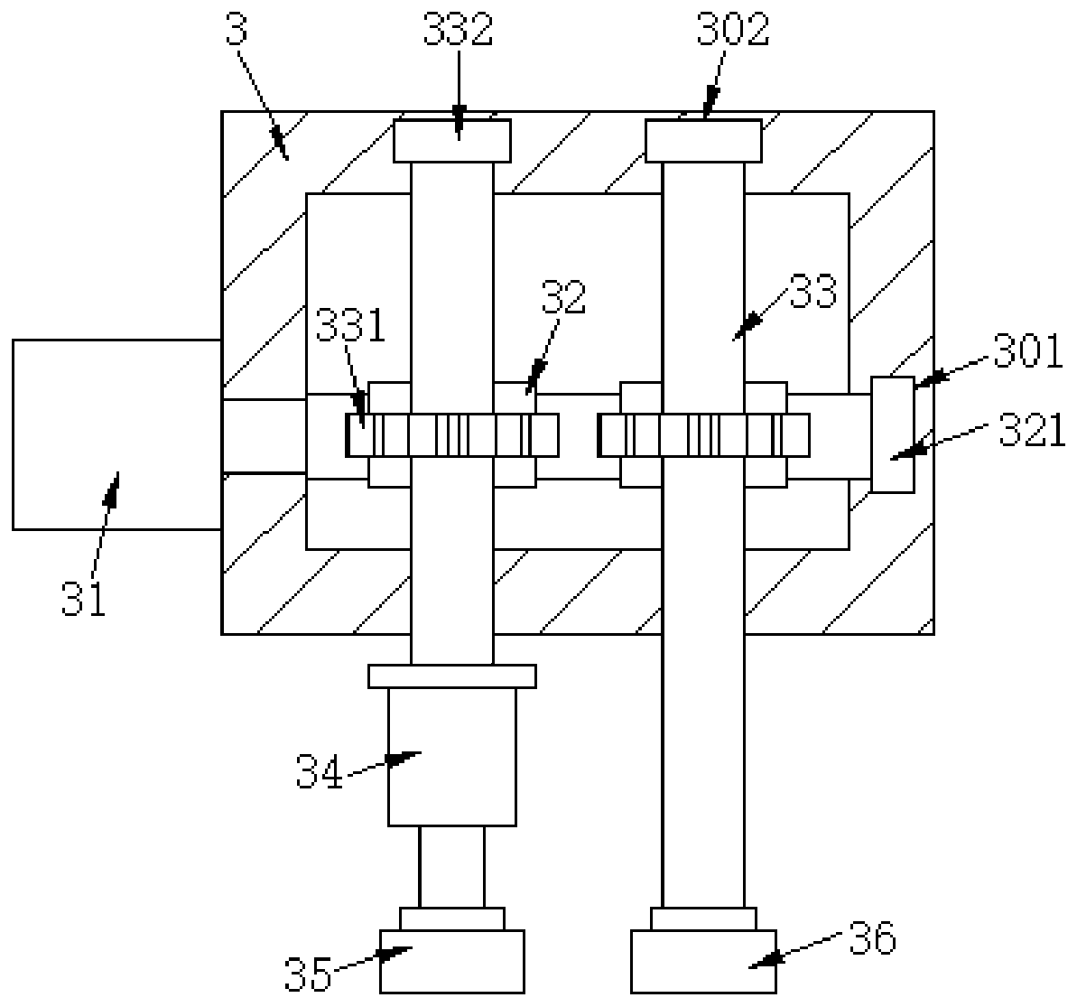
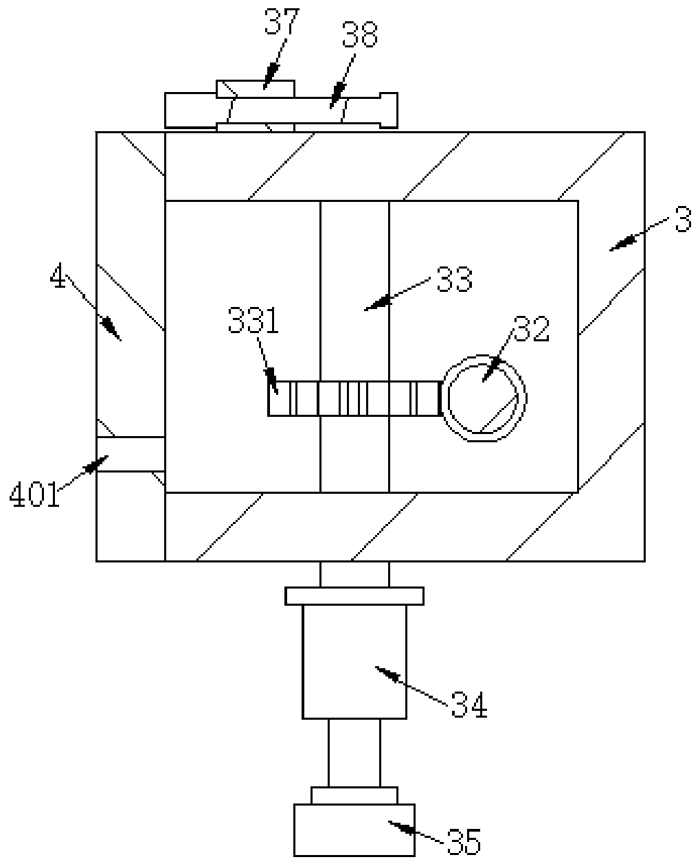
[0021] see Figure 1~5 , in the embodiment of the present invention, a kind of multistage grinder for mechanical equipment production, comprises workbench 1 and top plate 2, and the bottom of top plate 2 is provided with driving box 3, and the side wall of driving box 3 is fixedly connected with motor 31, and motor 31 is connected with external power supply Electrically connected, the output end of the motor 31 runs through the drive box 3, the output end of the motor 31 is fixedly connected with a worm 32, the inner side of the drive box 3 is connected with two rotating shafts 33, the outer walls of the two rotating shafts 33 are fixedly connected with a worm gear 331, and the two worm gears 331 are all meshed with the worm 32, the bottom ends of the two rotating shafts 33 run through the drive box 3, and the bottom ends of the two rotating shafts 33 extend to the outside of the driving box 3, and the bottom ends of one of the rotating shafts 33 are fixedly connected with an e...


PUM


Abstract

The invention belongs to the technical field of mechanical equipment, and particularly relates to a multi-stage grinding machine for mechanical equipment production. The multi-stage grinding machine for mechanical equipment production comprises a worktable and a top plate. A driving box is arranged at the bottom of the top plate. The side wall of the driving box is fixedly connected with a motor.The motor is electrically connected with an external power source, and the output end of the motor penetrates through the driving box and is fixedly connected with a worm. Two rotary shafts are rotationally connected with the inner side of the driving box, and the outer walls of the two rotary shafts are both fixedly connected with worm gears. The arranged motor can drive the worm to rotate, the worm drives the two worm gears to rotate, the rotary shafts can rotate in the driving box, and a rough grinding disc and a fine grinding disc are made to rotate. The transmission ratio of the worm gears and the worm is large, transmission is stable, the rough grinding disc can move up and down under the action of an electric telescopic rod, and the rough grinding disc and the fine grinding disc areprevented from being located on the same level, thereby being capable of grinding workpieces respectively.

Description

technical field [0001] The invention relates to the technical field of mechanical equipment, in particular to a multi-stage grinding machine for mechanical equipment production. Background technique [0002] Grinding machine is a kind of machine tool that uses abrasive tools to grind workpieces to obtain the required shape, size and precision machining surface. The processing action of grinding machine is grinding. The precise manufacture of mechanical parts depends on grinding work. [0003] The Chinese patent with the publication number (CN207139514U) discloses a grinding machine for multi-stage polishing. The patented technology adjusts the height of the grinding device through a hydraulic telescopic rod, and the moving device laterally displaces the grinding device to drive the first polishing disc and the second polishing disc. The disc polishes the polishing piece, the first polishing disc roughly polishes the polishing piece, and the second polishing disc performs fi...

Claims


Application Information

Patent Timeline
Patent Type & Authority Applications(China)
IPC IPC(8): B24B37/00B24B37/11B24B37/27B24B37/34B24B47/12B24B47/20
CPCB24B37/00B24B37/11B24B37/27B24B37/34B24B47/12B24B47/20
Inventor 谢勇达
Owner 云和县隆盛机械设计工作室
Why Eureka
Try Eureka