
Tool changing trolley and PCB drilling and milling machine

A technology of trolleys and gongs, which is applied to the processing of electrical components, insulating substrates/layers, and printed circuit manufacturing. It can solve problems such as the inability to realize automatic tool changes, reduce the utilization rate of equipment, and huge equipment, and achieve convenient recycling. and grinding management, improve equipment utilization rate, and improve work efficiency

Pending Publication Date: 2020-08-25
SUZHOU VEGA TECH CO LTD
View PDF0 Cites 4 Cited by
  • Summary
  • Abstract
  • Description
  • Claims
  • Application Information

AI Technical Summary

Problems solved by technology

[0003] At present, during the use of PCB drilling machines composed of PCB drilling machines and edge milling machines, the number of tool changes is usually reduced by increasing the capacity of the tool magazine on the equipment, thereby reducing manual operations. However, when changing tools, Manual tool change is still required, automatic tool change cannot be realized, and increasing the capacity of the tool magazine will also cause the entire equipment to be too large
[0004] Moreover, during the use of the existing PCB drilling machine, it is necessary to manually arrange the tools, and manually calculate the type and quantity of the tools required by the program. If there is no tool available during processing, it needs to be replaced manually, which is time-consuming and labor-intensive.
[0005] The tools of the existing PCB drilling machine are arranged on the workbench. When changing the tools or arranging the tools, the equipment must be stopped, and the workbench must be moved to the front, so that the operator can perform the work of changing the tools, which reduces the utilization rate of the equipment.

Method used


Image

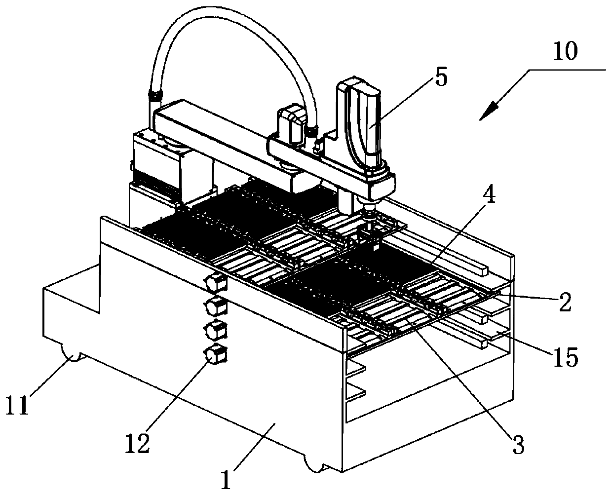
  • Tool changing trolley and PCB drilling and milling machine
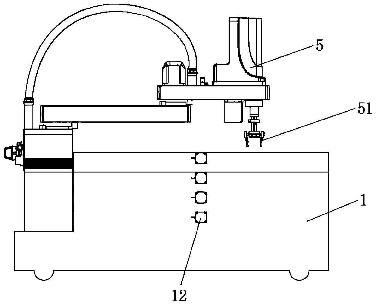
  • Tool changing trolley and PCB drilling and milling machine
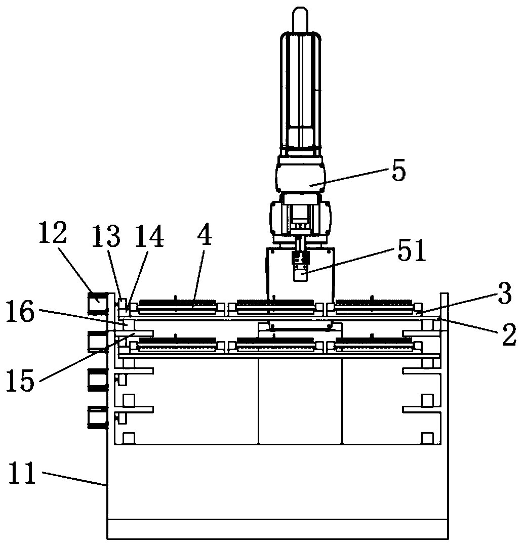
  • Tool changing trolley and PCB drilling and milling machine

Examples


Embodiment Construction

[0044] The present invention will be further described in detail below in conjunction with the accompanying drawings and embodiments. It should be understood that the specific embodiments described here are only used to explain the present invention, but not to limit the present invention. In addition, it should be noted that, for the convenience of description, only some structures related to the present invention are shown in the drawings but not all structures.

[0045] In the description of the present invention, unless otherwise clearly specified and limited, the terms "connected", "connected" and "fixed" should be understood in a broad sense, for example, it can be a fixed connection, a detachable connection, or an integrated ; It can be a mechanical connection or an electrical connection; it can be a direct connection or an indirect connection through an intermediary, and it can be the internal communication of two components or the interaction relationship between two ...


PUM


Abstract

The invention belongs to the technical field of PCB processing, and discloses a tool changing trolley which comprises a trolley body, at least two layers of supporting plates arranged in the trolley body in a sliding manner, a tool box placing plate mounted on the supporting plate and sliding along with the supporting plate, a tool box fixed on the toolbox placing plate and used for placing a tool, and a manipulator arranged on the trolley body and used for taking and placing the toolbox. According to the tool changing trolley, at least two layers of supporting plates are arranged, so that atleast two layers of tool boxes can be placed, multi-layer placement of tools is achieved, the tool placing number is increased, and the working efficiency of the tool changing trolley is improved. Theinvention further provides a PCB drilling and milling machine with the tool changing trolley, unmanned, intelligent and flexible tool changing procedures can be achieved, a movable tool holder is matched with the tool changing trolley, tools can be changed while machining is conducted, the equipment utilization rate is increased, and recovery and grinding management of the tools are facilitated.

Description

technical field [0001] The invention relates to the technical field of PCB board processing, in particular to a tool changing trolley and a PCB drilling machine. Background technique [0002] In the PCB industry, with the gradual maturity of equipment such as PCB drilling machines and edge milling machines, the processing scale in the factory is expanding day by day, and the need to reduce labor costs and improve the degree of automation has been put on the agenda. The concepts of automated workshops and unmanned workshops have gradually penetrated into practice. [0003] At present, during the use of PCB drilling machines composed of PCB drilling machines and edge milling machines, the number of tool changes is usually reduced by increasing the capacity of the tool magazine on the equipment, thereby reducing manual operations. However, when changing tools, Manual tool change is still required, and automatic tool change cannot be realized. Moreover, increasing the capacity ...

Claims


Application Information

Patent Timeline
IPC IPC(8): H05K3/00
CPCH05K3/0044H05K3/0047H05K3/0052
Inventor 黄齐齐庞士君常远
Owner SUZHOU VEGA TECH CO LTD
Learn More