Ultrasonic friction welding forming method for large-size amorphous alloys
An amorphous alloy, friction welding technology, applied in welding equipment, non-electric welding equipment, metal processing equipment and other directions, can solve the problems of heat dissipation and internal heat dissipation efficiency difference, uneven heat distribution of contact interface, poor welding quality, etc. Transfer and exchange, improve welding efficiency, reduce the effect of non-uniformity
- Summary
- Abstract
- Description
- Claims
- Application Information
AI Technical Summary
Problems solved by technology
Method used
Image
Examples
Embodiment 1
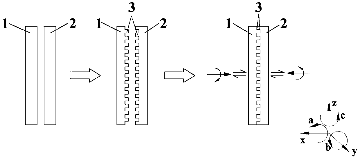
[0038] Such as figure 1 As shown, an ultrasonic friction welding forming method for large-scale amorphous alloys includes the following steps:
[0039]Step 1: Take the two amorphous alloys to be processed, and according to the welding requirements of the amorphous alloys, use milling to process the microstructure 3 at the interface to be welded between the first amorphous alloy 1 and the second amorphous alloy 2, Among them, the microstructure 3 is a rectangular structure, the composition of the first amorphous alloy 1 is Zr57Nb5Cu15.4Ni12.6Al10, the Tg is 405°C, and the Tx is 470°C, and the composition of the second amorphous alloy 2 is Zr58.5Nb2.8Cu15 .6Ni12.8Al10.3, Tg is 400°C, Tx is 480°C.
[0040] Step 2: clamp the first amorphous alloy 1 and the second amorphous alloy 2 on the welding system, so that the welding surface of the first amorphous alloy 1 and the welding surface of the second amorphous alloy 2 are in contact with each other.
[0041] Step 3: Set the main r...
Embodiment 2
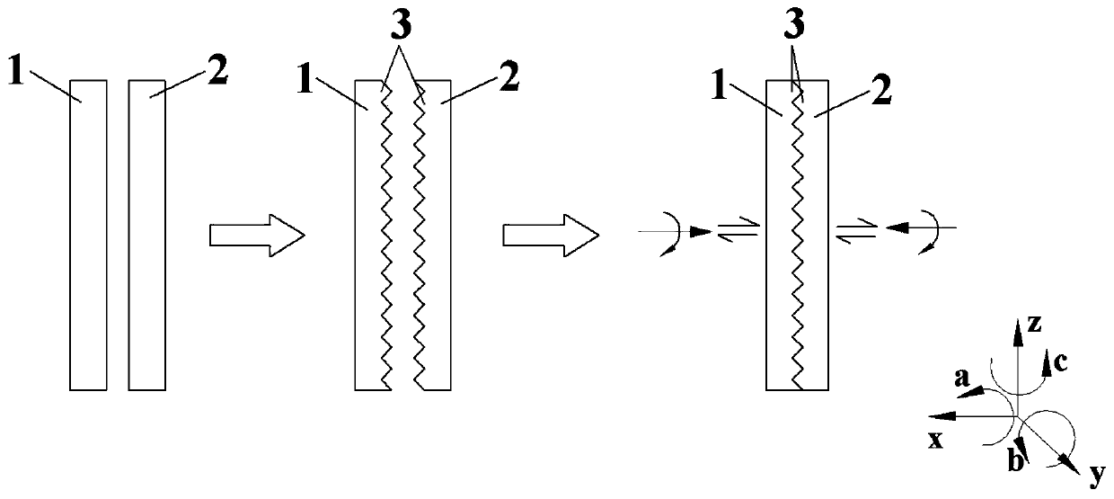
[0043] Such as figure 2 As shown, an ultrasonic friction welding forming method for large-scale amorphous alloys, including the following steps:
[0044] Step 1: Take the two amorphous alloys to be processed, and according to the welding requirements of the amorphous alloys, use laser processing to process the microstructure 3 at the interface to be welded between the first amorphous alloy 1 and the second amorphous alloy 2, wherein , the microstructure is a triangular structure, the components of the first amorphous alloy 1 and the second amorphous alloy 2 are both Ca65Li14.54Mg12.46Zn8, Tg is 35°C, and Tx is 105°C.
[0045] Step 2: Clamp the first amorphous alloy 1 and the second amorphous alloy 2 on the welding system, so that the welding surface of the first amorphous alloy and the welding surface of the second amorphous alloy are in contact with each other.
[0046] Step 3: Set the main rotation motion parameter of the first amorphous alloy 1 to rotate in the reverse di...
Embodiment 3
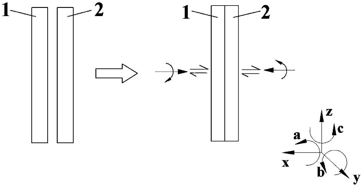
[0048] Such as image 3 As shown, an ultrasonic friction welding forming method for large-scale amorphous alloys, including the following steps:
[0049] Step 1: Take two amorphous alloys to be processed. The composition of the first amorphous alloy 1 is Zr44Ti11Cu10Ni10Be25, the Tg is 350°C, and the Tx is 471°C. The composition of the second amorphous alloy 2 is Zr35Ti30Be27.5Cu7.5 , Tg is 301°C, and Tx is 467°C.
[0050] Step 2: clamp the first amorphous alloy 1 and the second amorphous alloy 2 on the welding system, so that the welding surface of the first amorphous alloy 1 and the welding surface of the second amorphous alloy 2 are in contact with each other.
[0051] Step 3: Set the main rotation motion parameter of the first amorphous alloy 1 to rotate in the reverse direction of a, and the rotation speed is 300rpm, and the main rotation motion parameter of the second amorphous alloy 2 is to rotate along the a direction, and the rotation speed is 200rpm, The pressure d...
PUM
 Abstract
Description
Claims
Application Information
 - R&D
- Intellectual Property
- Life Sciences
- Materials
- Tech Scout
- Unparalleled Data Quality
- Higher Quality Content
- 60% Fewer Hallucinations
Browse by: Latest US Patents, China's latest patents, Technical Efficacy Thesaurus, Application Domain, Technology Topic, Popular Technical Reports.
© 2025 PatSnap. All rights reserved.Legal|Privacy policy|Modern Slavery Act Transparency Statement|Sitemap|About US| Contact US: help@patsnap.com


