
A device for collecting waste from grinding hardware based on gravity changes

A gravity change and collection device technology, applied in the field of hardware, can solve the problems of polluting the environment, accumulating on the bottom plate of cutting equipment, falling below the cutting platform, etc.

Active Publication Date: 2021-07-06
聊城开发区隆阳机械制造有限责任公司
View PDF2 Cites 0 Cited by
  • Summary
  • Abstract
  • Description
  • Claims
  • Application Information

AI Technical Summary

Problems solved by technology

[0003] The hardware in daily life needs to be polished or cut when we use it, especially in the mass production and manufacturing process of some large factories, but in the production process, the waste and slag generated during cutting or grinding and some smaller cutting workpiece It will fall under the cutting platform, which will bring a lot of inconvenience to normal production activities, increase the work intensity and reduce the work efficiency, and the accumulation of waste and slag in the cutting machine will pollute the environment and affect the appearance; traditional hardware cutting and polishing The equipment often has the problem of iron filings splashing and then accumulating on the bottom plate of the cutting equipment. Since the iron filings have a high recycling value at the same time, these cutting iron filings often need to be recycled again in the later stage, which undoubtedly greatly increases the cost. Labor intensity
[0004] Therefore, we propose a device for collecting scraps from grinding hardware based on gravity changes. Through the built-in gravity sensing system, the scraps generated when cutting and grinding hardware are collected, avoiding the traditional cutting and grinding equipment, which does not have The function of recycling grinding waste; it solves the problem that traditional metal cutting and grinding equipment often has iron filings splashing and then piled up on the bottom plate of the cutting equipment

Method used


Image

  • A device for collecting waste from grinding hardware based on gravity changes
  • A device for collecting waste from grinding hardware based on gravity changes
  • A device for collecting waste from grinding hardware based on gravity changes

Examples


Embodiment Construction

[0037] The following will clearly and completely describe the technical solutions in the embodiments of the present invention with reference to the accompanying drawings in the embodiments of the present invention. Obviously, the described embodiments are only some, not all, embodiments of the present invention. Based on the embodiments of the present invention, all other embodiments obtained by persons of ordinary skill in the art without making creative efforts belong to the protection scope of the present invention.

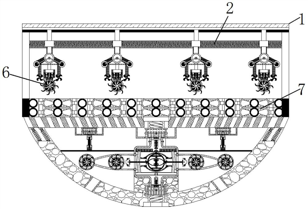
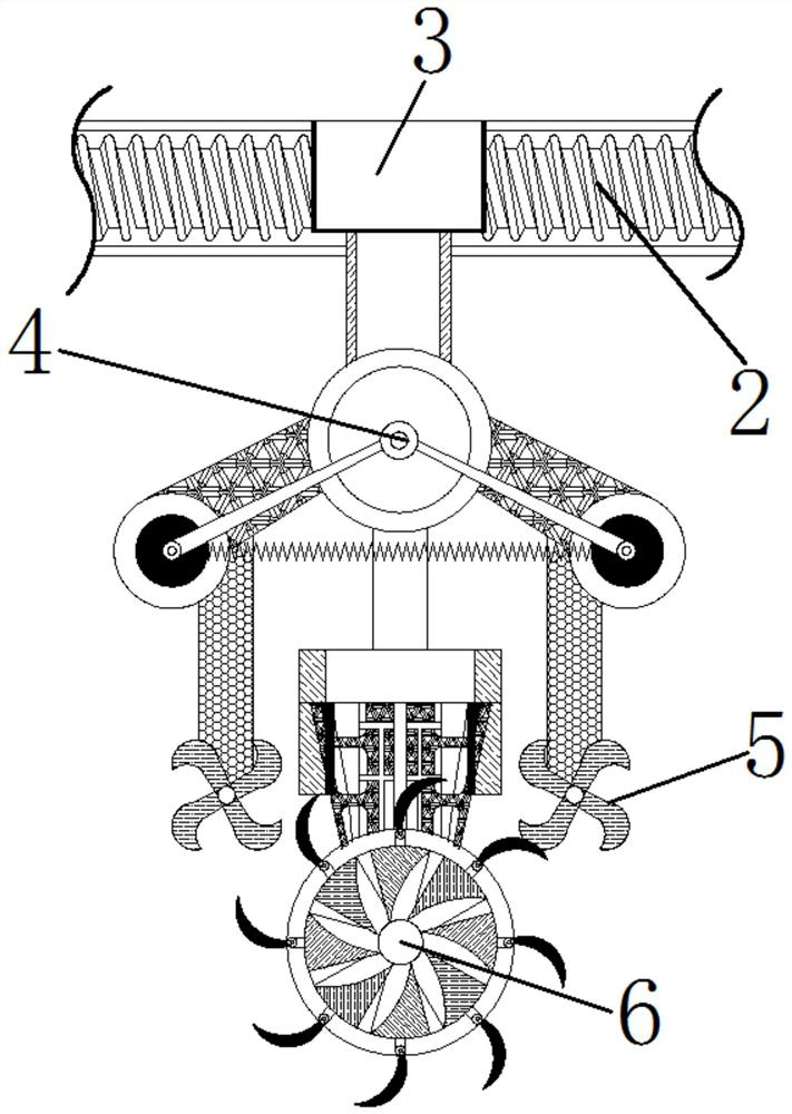
[0038] see Figure 1-17 , a device for collecting scraps from grinding hardware based on changes in gravity, including a device main body 1, a movable screw 2 is installed on the movable part of the device main body 1, a slider 3 is threaded on the outer side of the movable screw 2, and the lower part of the slider 3 moves The installation block 4 is connected, and the sub-grinding knife 5 and the main grinding knife 6 are movable installed under the installat...


PUM


Abstract

The present invention relates to the field of hardware technology, and discloses a device for collecting scraps from grinding hardware based on changes in gravity. The bottom of the gravity sensor is movably connected with a pressing spring, the bottom of the pressing spring is movably connected with a pressing component, the bottom of the pressing component is movably connected with a connection spring, the bottom of the connection spring is movably connected with a connection switch, and the bottom of the second gravity sensor is movably connected There is a trigger spring, and a trigger switch is flexibly connected to the bottom of the trigger spring. Based on the change of gravity, the waste scrap collection device for hardware grinding is realized. By absorbing all the iron scraps into the scrap storage bag, workers can directly remove the scrap storage bag and then achieve the purpose of collecting scrap iron scraps, avoiding the traditional Advanced cutting and grinding equipment does not have the function of recycling grinding waste.

Description

technical field [0001] The invention relates to the technical field of hardware, in particular to a device for collecting scraps from grinding hardware based on changes in gravity. Background technique [0002] Hardware: Traditional hardware products, also known as hardware, refer to five metals including gold, silver, copper, iron and tin. After manual processing, they can be made into works of art or metal devices such as knives and swords. Hardware in modern society is more extensive, such as Hardware tools, hardware parts, daily hardware, construction hardware and security supplies, etc. [0003] The hardware in our daily life needs to be polished or cut when we use it, especially in the mass production and manufacturing process of some large factories, but in the production process, the waste and slag generated during cutting or grinding and some smaller cutting workpieces It will fall under the cutting platform, which will bring a lot of inconvenience to normal produc...

Claims


Application Information

Patent Timeline
Patent Type & Authority Patents(China)
IPC IPC(8): B24B27/00B24B47/04B24B55/06B24B41/02B24B55/12B24B49/00B24B41/04
CPCB24B27/0076B24B41/02B24B41/04B24B47/04B24B49/00B24B55/06B24B55/12
Inventor 徐惠
Owner 聊城开发区隆阳机械制造有限责任公司
Learn More