Contour control method for synchronous cross-coupling robot

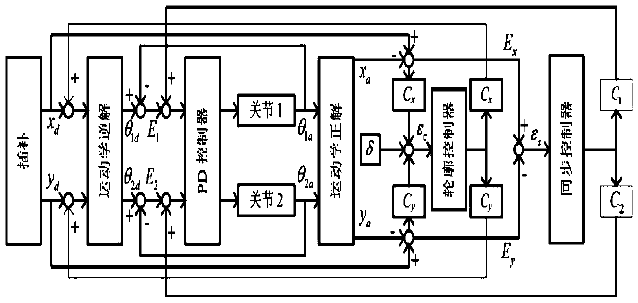
A contour control and cross-coupling technology, which is applied in the direction of program control manipulators, manipulators, manufacturing tools, etc., can solve problems such as the inability to apply industrial robot systems, achieve the effects of improving control effects, ensuring tracking accuracy, and reducing contour errors

Active Publication Date: 2020-08-28
XIAN AERONAUTICAL POLYTECHNIC INST
View PDF8 Cites 3 Cited by
  • Summary
  • Abstract
  • Description
  • Claims
  • Application Information

AI Technical Summary

Problems solved by technology

[0003] The purpose of the present invention is to provide a synchronous cross-coupling robot contour control method, which solves the problem that the traditional cross-coupling control in the prior art cannot be applied to industrial robot systems

Method used


Image

  • Contour control method for synchronous cross-coupling robot
  • Contour control method for synchronous cross-coupling robot
  • Contour control method for synchronous cross-coupling robot

Examples


Embodiment 1

[0095] The contour trajectory is elliptical, and the radius of the expected center contour trajectory is set to 8cm, the initial position of the end effector is (0.02, 0.35), and the setting of the initial position of the end ensures that the robot is always in the working space during the movement process. The specific trajectory The equation is:

[0096]

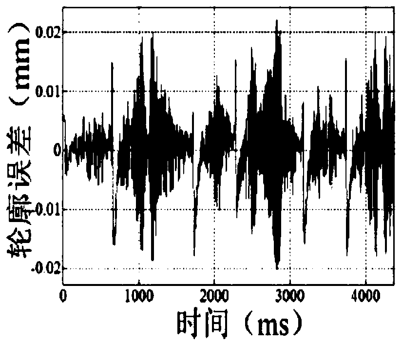
[0097]The angular velocity ω of the circular trajectory is set to low speed and medium speed to conduct experiments respectively. Firstly, the low speed state of ω=0.02rad / s is set, and the obtained motion contour error changes and experimental data are as follows: Figure 2a , Figure 2b , as shown in Table 2:

[0098] Table 2 Experimental data of low-speed circular trajectory

[0099]

[0100] The results of comparative experiments show that the contour error of synchronous cross-coupling control is significantly reduced, the maximum contour error is reduced by 3.12 μm, and the root mean square value is reduced b...

Embodiment 2

[0107] The contour trajectory is elliptical. Set the long radius of the expected circle center contour trajectory to 8cm, the short radius to 4cm, and the initial position of the end effector (0.02, 0.35), which effectively ensures the movement process of the system in the working space. The specific trajectory The equation is:

[0108]

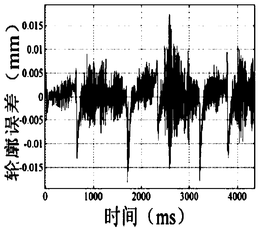
[0109] The motion contour error change and experimental data obtained by setting ω=0.02rad / s are as follows Figure 4a , Figure 4b And as shown in Table 4:

[0110] Table 4 Experimental data of low-speed elliptical trajectory

[0111]

[0112] Similarly, the comparison experiment results of the elliptical profile show that compared with the position loop cross-coupling control, the maximum error of the profile using the synchronous cross-coupling control is reduced by 6.21 μm, and the root mean square value is reduced by 1.11 μm.

[0113] It can be concluded that, for elliptical contours with more complex shapes, synchronous cross-c...


PUM


Abstract

The invention discloses a contour control method for a synchronous cross coupling robot. The method includes the following steps: acquiring expected positions xd and yd of a working space, carrying out kinematic inverse solution operation on the expected positions xd and yd, and outputting expected positions theta1d and theta2d of a joint space; performing difference value operation on the expected positions theta1d and theta2d of the joint space and the actual positions theta1a and theta2a of the joint space, and then outputting an X-axis joint space tracking error E1 and a y-axis joint spacetracking error E2; subjecting the x-axis joint space tracking error E1 and the y-axis joint space tracking error E2 to operation by a PD controller, and then driving a motor to operate; meanwhile, calculating the contour error epsilonc and the synchronization error epsilons respectively according to the x-axis joint space tracking error E1 and the y-axis joint space tracking error E2, subjectingthe contour error epsilonc and the synchronization error epsilons to operation by a contour controller and a synchronization controller respectively, and performing corresponding gain compensations ona position ring of the working space and a speed ring of the joint space respectively. The contour error can be further reduced, the control effect is improved, and the tracking precision of the robot system is further ensured.

Description

technical field [0001] The invention belongs to the technical field of robot control methods, and relates to a synchronous cross-coupling robot contour control method. Background technique [0002] With the rapid development of robot control technology and the increasing perfection of robot functions, more and more robots are widely used in processing and manufacturing fields such as grinding and spraying. Not only that, the requirements for robot motion control accuracy are also getting higher and higher. In this case, in addition to considering the original position tracking error in the design of the robot system controller, the contour error must also be considered as an important performance indicator of the system, which determines that the contour error must be considered in the controller design the size of. However, traditional contour control methods are generally applicable to orthogonal structure systems or CNC machine tool systems, while the research on contour...

Claims


Application Information

Patent Timeline
Patent Type & Authority Applications(China)
IPC IPC(8): B25J9/16
CPCB25J9/1628
Inventor 王瑜瑜刘少军
Owner XIAN AERONAUTICAL POLYTECHNIC INST
Why Eureka
Try Eureka