Winding device of textile equipment

A technology of winding device and textile equipment, which is applied in the direction of textiles and papermaking, winding strips, transportation and packaging, etc. It can solve the problems of textile pulling and other problems, and achieve the effects of avoiding pulling damage, convenient use, and improving quality

Inactive Publication Date: 2020-08-28
钱炜
View PDF14 Cites 4 Cited by
  • Summary
  • Abstract
  • Description
  • Claims
  • Application Information

AI Technical Summary

Problems solved by technology

[0004] The purpose of the present invention is to solve the problem of pulling the textile cloth when the winding diameter of the reel is large, and propose a winding device for textile equipment

Method used


Image

  • Winding device of textile equipment
  • Winding device of textile equipment
  • Winding device of textile equipment

Examples


Embodiment 1

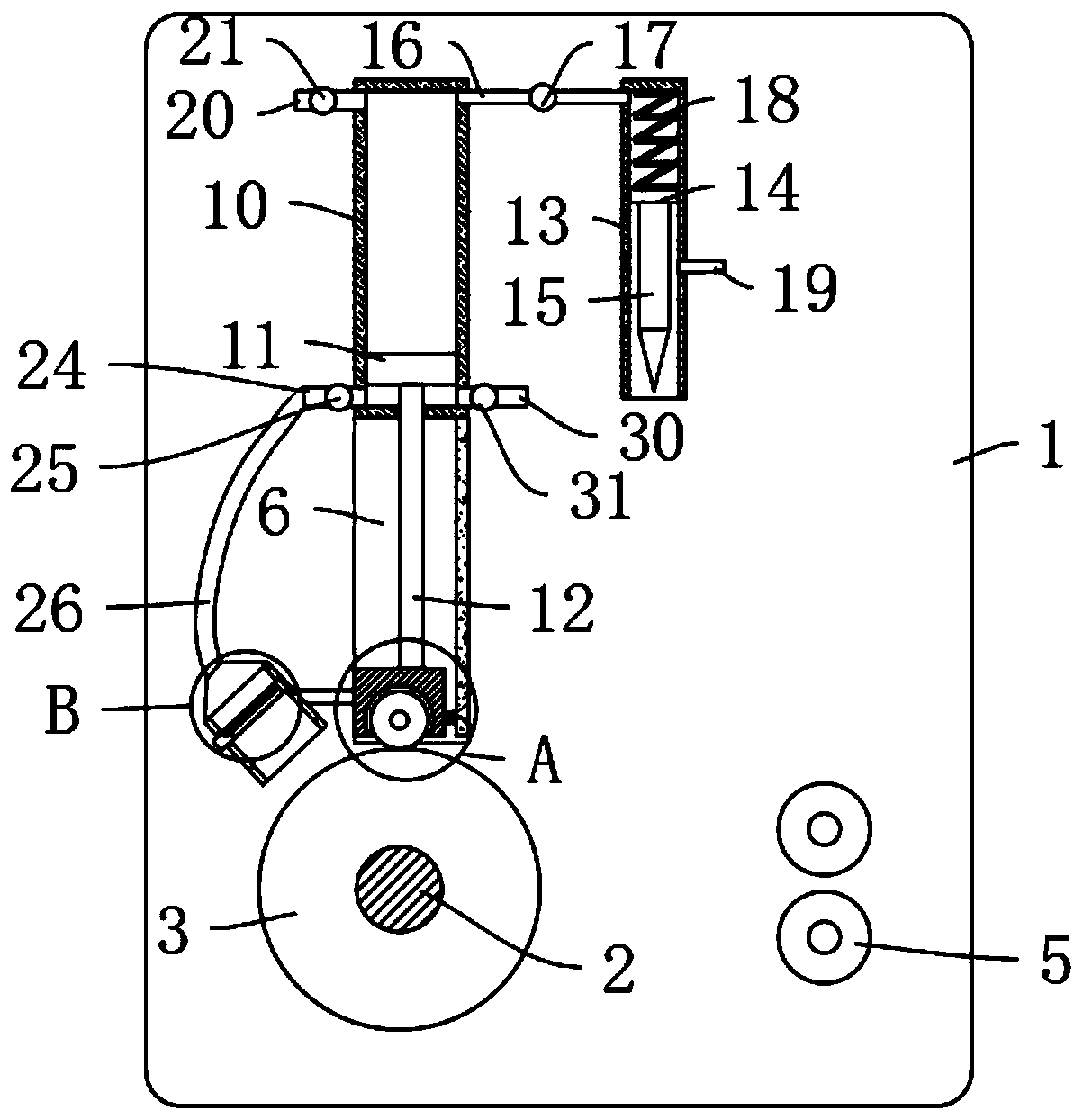
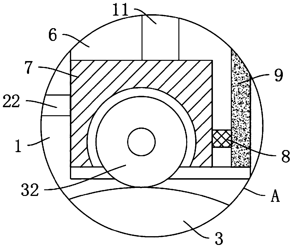
[0028] refer to figure 1 , figure 2 , Figure 4 , a winding device for textile equipment, comprising two symmetrically arranged support vertical boards 1, a rotating shaft 2 is rotatably connected between the two supporting vertical boards 1, and a reel 3 is fixedly connected to the outer wall of the rotating shaft 2, and the support vertical board 1 The outer wall is fixedly installed with a driving motor 4 fixedly connected to one end of the rotating shaft 2, and two guide rollers 5 are fixedly connected between the opposite side walls of the two support vertical plates 1, and the opposite side walls of the two support vertical plates 1 are provided with Slideway 6, between two slideways 6, slide block 7 that fits with the outer wall of the upper end of reel 3 is slidably connected, and the side wall of slideway 6 is provided with sliding rheostat 9, and the side wall of slide block 7 is fixedly connected with sliding block 7. The rheostat slide 8 matched with the rheosta...

Embodiment 2

[0033] refer to Figure 1-2 , is basically the same as Embodiment 1, furthermore: the automatic cut-off mechanism includes a first piston 11 slidably connected in the energy storage box 10, the first piston 11 is fixedly connected with the slider 7 through a slide rod 12, and the energy storage The upper end of the box 10 and the cutting box 13 is communicated through a connecting pipe 16. The cutting box 13 is slidably connected with a second piston 14 with a blade 15 connected to the lower end. The middle part of the connecting pipe 16 is provided with an overflow valve 17. The upper end of the energy storage box 10 is provided with a first suction pipe 20, the first suction pipe 20 is provided with a first check valve 21, the lower end of the energy storage box 10 is provided with a second suction pipe 30, and the second suction pipe 30 is provided with a There is a second one-way valve 31 in the opposite direction to the first one-way valve 21. When the winding of the text...

Embodiment 3

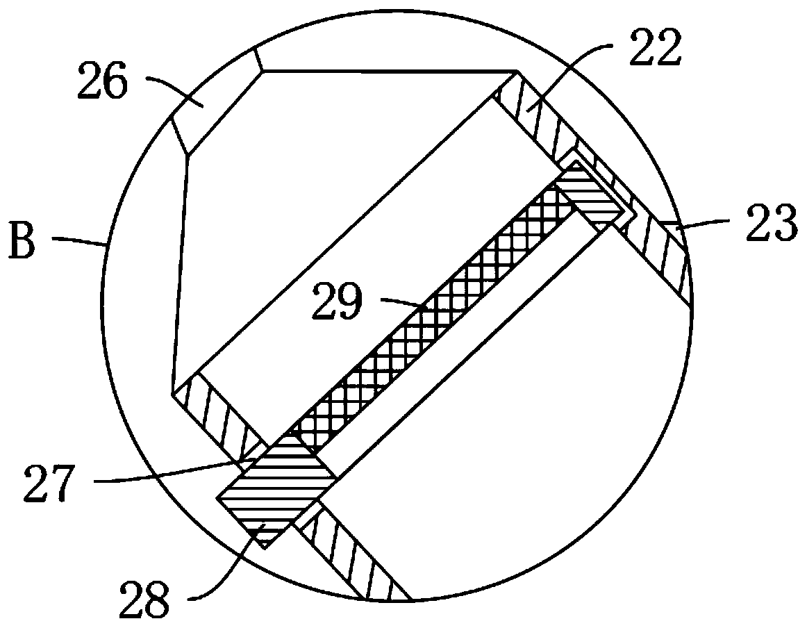
[0037] refer to figure 1 and image 3 , is basically the same as Embodiment 1, furthermore: the side wall of the slider 7 is fixedly connected with the dust collection cover 22 through the connecting plate 23, the opening of the dust collection cover 22 is inclined to the outer wall direction of the reel 3, and the energy storage box 10 The lower end side wall of the lower end side wall is fixedly connected with the third suction pipe 24, and the third check valve 25 opposite to the direction of the second check valve 31 is installed in the third suction pipe 24, and the dust suction cover 22 is connected with the third suction pipe. 24 are communicated with each other through telescopic hose 26, the material of telescopic hose 26 is rubber, and the inside of dust collection cover 22 is connected with filter screen 29, during the reel winding period, that is, during the sliding block 7 upwards, the third suction The trachea 24 sucks air through the telescopic hose 26 to the d...


PUM


Abstract

The invention discloses a winding device of textile equipment, and belongs to the field of textile equipment. The winding device of the textile equipment comprises two supporting vertical plates whichare symmetrically arranged, a rotating shaft is rotatably connected between the two supporting vertical plates, a drum is fixedly connected to the positioning outer wall of the rotating shaft, slideways are correspondingly formed in the opposite side walls of the two supporting vertical plates, a sliding block which is in fit with the outer wall of the upper end of the drum is slidably connectedbetween the two slideways, slide rheostats are arranged on the side walls of the slideways, a variable resistance sliding sheet matched with the slide rheostats is fixedly connected to the side wall of the sliding block, an energy storage box and a cutting box are fixedly connected between the two supporting vertical plates, and automatic cutting mechanisms connected with the sliding block are arranged in the energy storage box and the cutting box. According to the winding device, the rotation speed of the drum is controlled while winding a textile cloth, so as to prevent the pulling damage ofthe textile cloth when the diameter of the drum is large, the textile cloth at the upper end of the drum can further be automatically cut off, and using is more convenient.

Description

technical field [0001] The invention relates to the technical field of textile equipment, in particular to a winding device for textile equipment. Background technique [0002] Textile machinery, that is, textile equipment, is the various mechanical equipment required to process natural fibers or chemical fibers into textiles. There are many types of textile machinery, which are usually classified according to the production process, including: spinning equipment, weaving equipment, printing and dyeing equipment, finishing Equipment, chemical fiber spinning equipment, silk reeling equipment and non-woven fabric equipment. [0003] After the textile equipment completes the production of fabrics and fabrics, the fabric needs to be wound on the reel, but the existing fabric winding device found in use that the more the number of turns of the reel, the larger the diameter of the reel , so that the length of the fabric required for each winding of the reel is longer, but the con...

Claims


Application Information

Patent Timeline
Patent Type & Authority Applications(China)
IPC IPC(8): B65H18/10B65H23/198B65H19/26D06G1/00
CPCB65H18/10B65H19/26B65H23/1955B65H23/198B65H2701/1133D06G1/00
Inventor 不公告发明人
Owner 钱炜
Why Eureka
Try Eureka