Three-stage screw compressor

A screw compressor, compression chamber technology, applied in mechanical equipment, machines/engines, liquid fuel engines, etc., can solve the problems of reduced bearing operating life, damage to the main engine, seizure, rotor wear and deformation, etc., to extend service life, improve Service life, effect of reducing compression ratio and differential pressure

Inactive Publication Date: 2020-08-28
浙江佳成机械有限公司 +1
View PDF9 Cites 3 Cited by
  • Summary
  • Abstract
  • Description
  • Claims
  • Application Information

AI Technical Summary

Problems solved by technology

As a result, the operating life of the bearing is greatly reduced, and the rotor is severely worn and deformed under long-term operation, which will damage the main engine and cause it to die, thereby reducing its practicability

Method used


Image

  • Three-stage screw compressor
  • Three-stage screw compressor
  • Three-stage screw compressor

Examples


Embodiment Construction

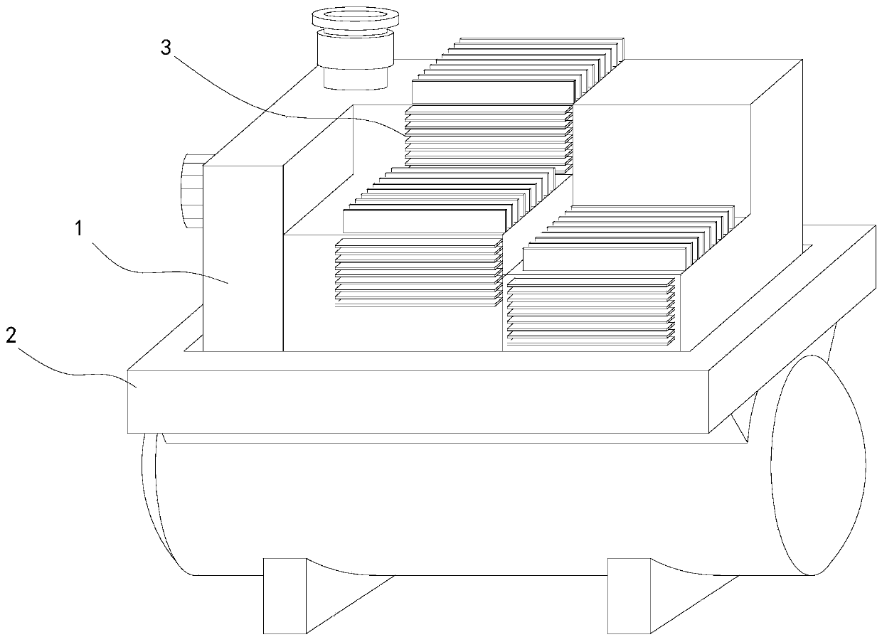
[0031] See Figure 1 to 10 , A schematic diagram of the plane structure and a three-dimensional structure diagram of a three-stage screw compressor.

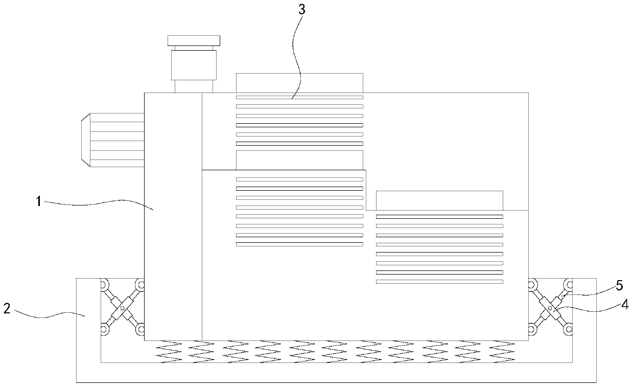
[0032] A three-stage screw compressor includes a device body 1, a first compression chamber 7 is opened at the upper end of the device body 1, a water flow groove 6 is opened in the device body 1 relative to the outside of the first compression chamber 7, and the lower end of the device body 1 is fixedly installed A damping base 2 and a heat sink 3 are fixedly installed on the outside of the device main body 1.

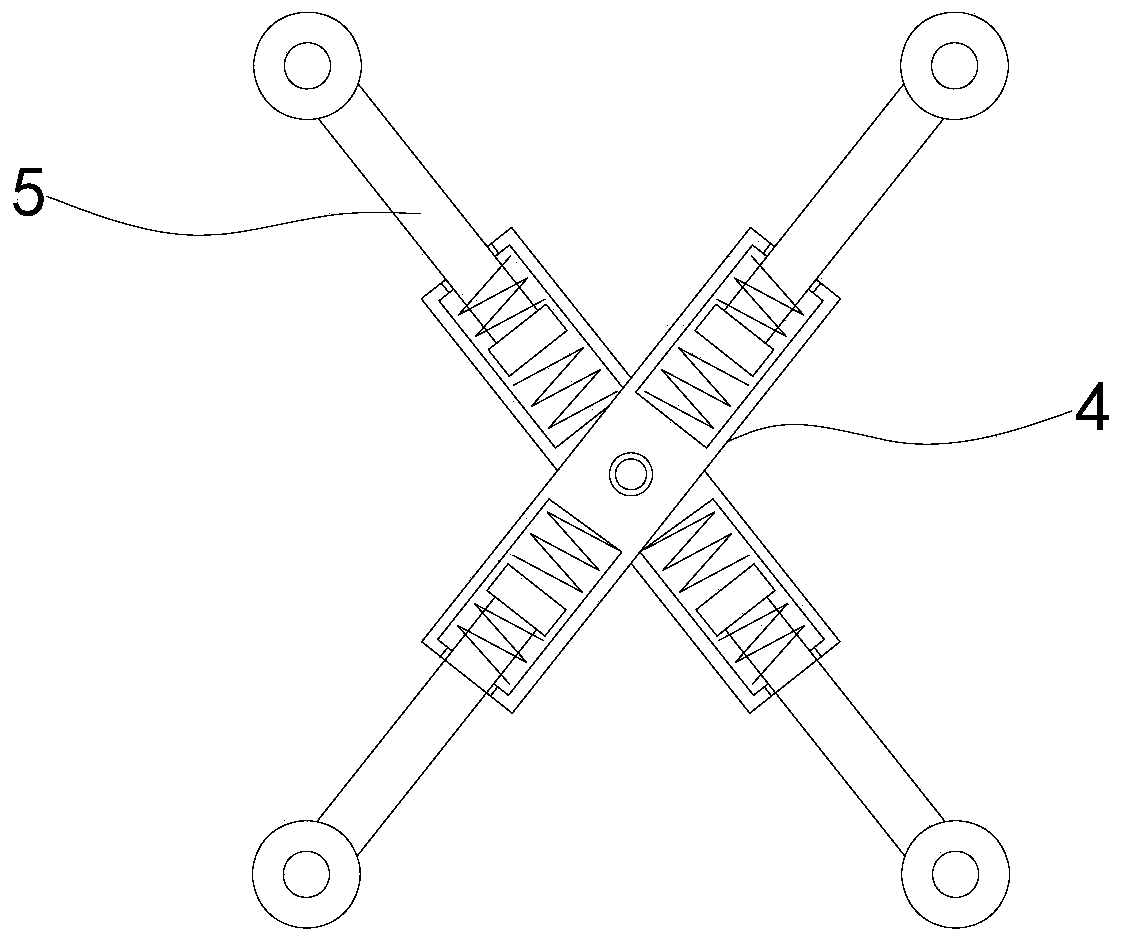
[0033] In specific implementation, the inner left and right sides of the shock-absorbing base 2 are fixedly installed with buffer outer rods 4, and the buffer outer rod 4 is movably sleeved with a buffer inner rod 5, so that when the device body 1 generates left and right vibrations, it can overcome The force of the spring presses the inner buffer rod 5 into the outer buffer rod 4, thereby absorbing the shock.

[0034] In sp...


PUM


Abstract

The invention relates to the field of screw compressors, in particular to a three-stage screw compressor which comprises a device main body; a first compressing cavity is formed in the upper end of the interior of the device main body; a water flow groove is formed in a position, opposite to the outer side of the first compressing cavity, of the device main body; a damping base is fixedly mountedat the lower end of the device main body; and a radiating fin is fixedly mounted on the outer side of the device main body. Male rotors in the first compressing cavity and a second compressing cavityare meshed with the two sides of the driving gear of a driving motor through driven gears, so that the driving motor can simultaneously drive the first compressing cavity and the second compressing cavity to start to compress the air, power consumption is reduced, the air compressed in the first compressing cavity enters the second compressing cavity through a first ventilating passage to be compressed once more, the compression ratio of each stage is reduced, the differential pressure of each stage is reduced, and the volumetric efficiency of the compressing process is further improved to enable the load of a bearing to be smaller, and the service life of the bearing is prolonged.

Description

Technical field [0001] The invention relates to the field of screw compressors, in particular to a three-stage screw compressor. Background technique [0002] Screw compressors are divided into single screw compressors and twin screw compressors. They were first proposed by German H. Krigar in 1878. It was not until 1934 that A. Lysholm of the Royal Institute of Technology in Sweden established the technology and began to apply it in industry. Achieve rapid development. [0003] However, in the existing two-stage screw compressor, the suction and discharge pressure ratio and pressure difference of the main engine at this time are huge when the discharge pressure is 2.5 to 4.0 mpa. As a result, the operating life of the bearing is greatly reduced, causing serious wear and deformation of the rotor under long-term operation, which will destroy the host and seize, thereby reducing its practicality. Summary of the invention [0004] A three-stage screw compressor to increase the servic...

Claims


Application Information

Patent Timeline
Patent Type & Authority Applications(China)
IPC IPC(8): F04C18/16F04C29/04F04C29/00
CPCF04C18/165F04C29/00F04C29/0007F04C29/04
Inventor 姜勇林圣玉袁野
Owner 浙江佳成机械有限公司
Why Eureka
Try Eureka