


Quick Research
Generate reliable direction feasibility study reports for your R&D in just a few steps.

Technical Q&A
Discover and master advanced knowledge NOW. Basics, ideas, possibilities, all at once.

Find Solutions
As an expert in R&D theories, this can generate solutions to your technical problems instantly.

Evaluate Feasibility
Analyze your overall solution with one click, know your potential R&D risks in advance.

Monitor Landscape
Get weekly tech updates, stay abreast of the latest tech innovations and key insights.
Low-power-consumption flow self-adaptive hydraulic position closed-loop control system and method
An adaptive control, closed-loop control technology, applied in the safety of fluid pressure actuation system, fluid pressure actuation system components, fluid pressure actuation device, etc. Poor pollution ability, etc.
- Summary
- Abstract
- Description
- Claims
- Application Information
AI Technical Summary
Problems solved by technology
Method used
Image

Examples
Embodiment 1
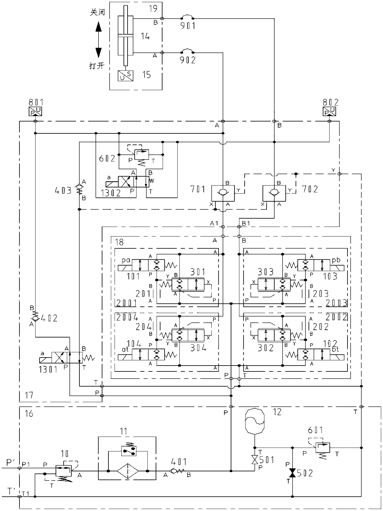
[0031] refer to figure 1 , is a structural schematic diagram of Embodiment 1 of the present invention, a low-power flow adaptive hydraulic position closed-loop control system, which is characterized in that it includes a decompression energy storage filter unit 16, an emergency shutdown unit 17, a hydraulic closed-loop control unit 18 and an execution One end of the decompression energy storage filter unit 16 communicates with the hydraulic station through the oil pipeline, and one end of the emergency shutdown unit 17 and the hydraulic closed-loop control unit 18 are connected in parallel on the other end oil pipeline of the decompression energy storage filter unit 16 , the other end of the emergency shutdown unit 17 and the hydraulic closed-loop control unit 18 communicate with the actuator unit 19 through the oil pipeline.
[0032] The further decompression energy storage filter unit 16 is used for the decompression and filtration of hydraulic pressure oil and the supply of...
Embodiment 2
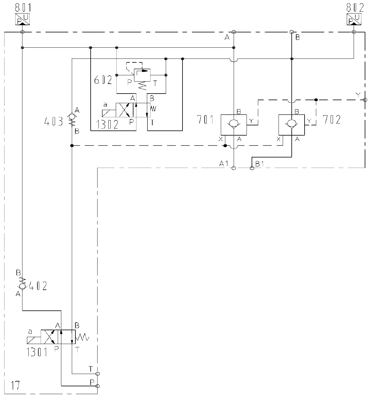
[0034]Compared with Embodiment 1, the difference of this embodiment is that one end of the decompression energy storage filter unit 16 is provided with an oil inlet P1 and an oil return port T1, and the other end of the decompression energy storage filter unit 16 is provided with Oil port P and oil port T, one end of the emergency closing unit 17 is provided with oil port P and oil port T, and the other end of the emergency closing unit 17 is provided with oil port A, oil port B and oil port A1 and oil port B1, hydraulic pressure One end of the closed-loop control unit 18 is provided with an oil port P and an oil port T, the other end of the hydraulic closed-loop control unit 18 is provided with an oil port A and an oil port B, and one end of the actuator unit 19 is provided with an oil port A and an oil port B, The hydraulic station is provided with a pressure oil port P' of the hydraulic station and an oil return port T' of the hydraulic station. The oil inlet P1 of the decom...
Embodiment 3
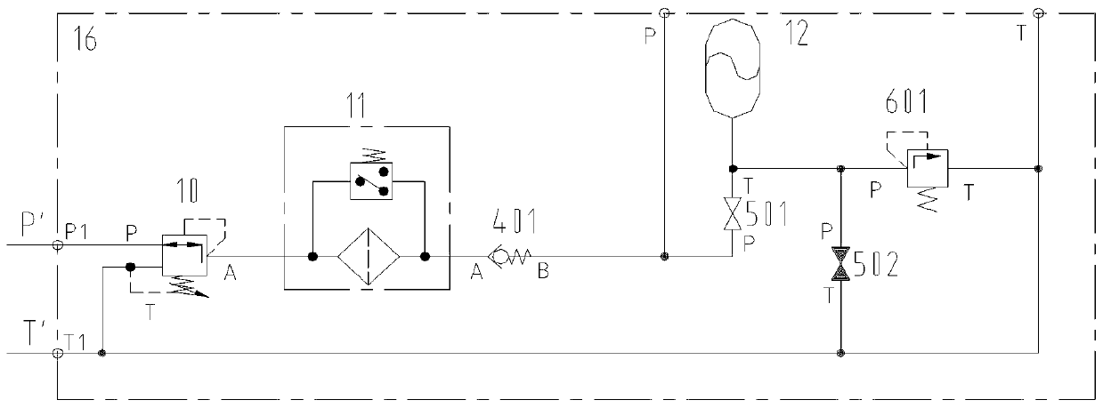
[0036] refer to figure 2 Compared with Embodiment 2, the difference of this embodiment is that the decompression energy storage filter unit 16 includes a three-way decompression valve 10, a filter 11, a one-way valve 401, a first ball valve 501, a first Two ball valves 502, an accumulator 12 and a first relief valve 601, one end of the three-way pressure reducing valve 10 communicates with the pressure oil port P' of the hydraulic station and the oil return port T' of the hydraulic station through the oil pipeline, and the three-way decompression The other end of the valve 10 communicates with one end of the filter 11 through the oil pipeline, the other end of the filter 11 communicates with one end of the check valve 401 through the oil pipeline, and the other end of the check valve 401 communicates with one end of the first ball valve 501 through the oil pipeline. The other end of the ball valve 501 communicates with the second ball valve 502 and one end of the first relief...
PUM
 Abstract
Description
Claims
Application Information
 - R&D Engineer
- R&D Manager
- IP Professional
- Industry Leading Data Capabilities
- Powerful AI technology
- Patent DNA Extraction
Browse by: Latest US Patents, China's latest patents, Technical Efficacy Thesaurus, Application Domain, Technology Topic, Popular Technical Reports.
© 2024 PatSnap. All rights reserved.Legal|Privacy policy|Modern Slavery Act Transparency Statement|Sitemap|About US| Contact US: help@patsnap.com