Strong heat dissipation type high-voltage switch cabinet and working method thereof

A high-voltage switchgear, heat-dissipating technology, applied in substation/switch layout details, substation/switchgear cooling/ventilation, electrical components, etc. and other problems, to ensure the effect of heat dissipation, rapid heat dissipation, and saving drive energy consumption

Inactive Publication Date: 2020-08-28
ANHUI WANHUA ELECTRICAL TECHNOLOGY CO LTD
View PDF1 Cites 2 Cited by
  • Summary
  • Abstract
  • Description
  • Claims
  • Application Information

AI Technical Summary

Problems solved by technology

[0003] The prior art has disclosed application number 201010263476.6, a heat sink for a circuit board, including a heat sink; the heat sink includes a heat sink bracket, a fan, a heat sink cover, a radiator, and fixing screws; the radiator and the fan connected to each other and installed together on the cooling device bracket; the bottom of the cooling device bracket is provided with a first through hole; the fan includes fan blades and a second through hole; the fan blades are arranged inside the fan, and the The second through hole is arranged at the bottom of the fan; the second through hole on the fan communicates with the first through hole; the heat sink cover plate is arranged on the heat sink bracket and fixed by fixing screws; the radiator cover plate There is a gap on it; the cover plate of the cooling device covers the fan and the radiator; the radiator communicates with the gap to realize that the hot air is discharged from the cooling device; but the heat dissipation effect of the existing switchgear is poor, and the During heat dissipation, the inside of the switchgear is exposed to the air, and dust and debris in the outside air enter the switchgear and affect the practical performance. When the humidity of the external environment is high, the humid environment will also cause the switchgear to be easily damaged

Method used


Image

  • Strong heat dissipation type high-voltage switch cabinet and working method thereof
  • Strong heat dissipation type high-voltage switch cabinet and working method thereof
  • Strong heat dissipation type high-voltage switch cabinet and working method thereof

Examples


Embodiment Construction

[0026]The technical solutions of the present invention will be clearly and completely described below in conjunction with the embodiments. Apparently, the described embodiments are only some of the embodiments of the present invention, not all of them. Based on the embodiments of the present invention, all other embodiments obtained by persons of ordinary skill in the art without creative efforts fall within the protection scope of the present invention.

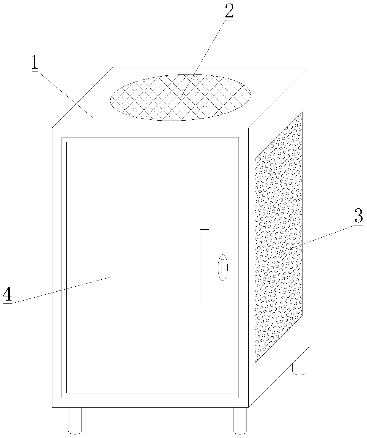
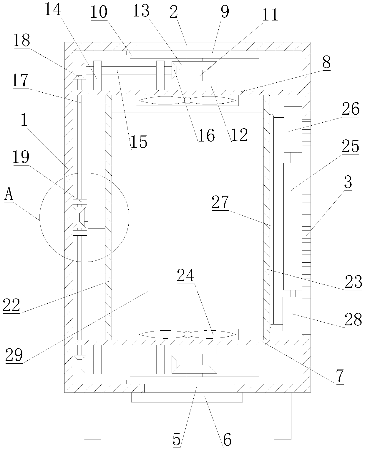
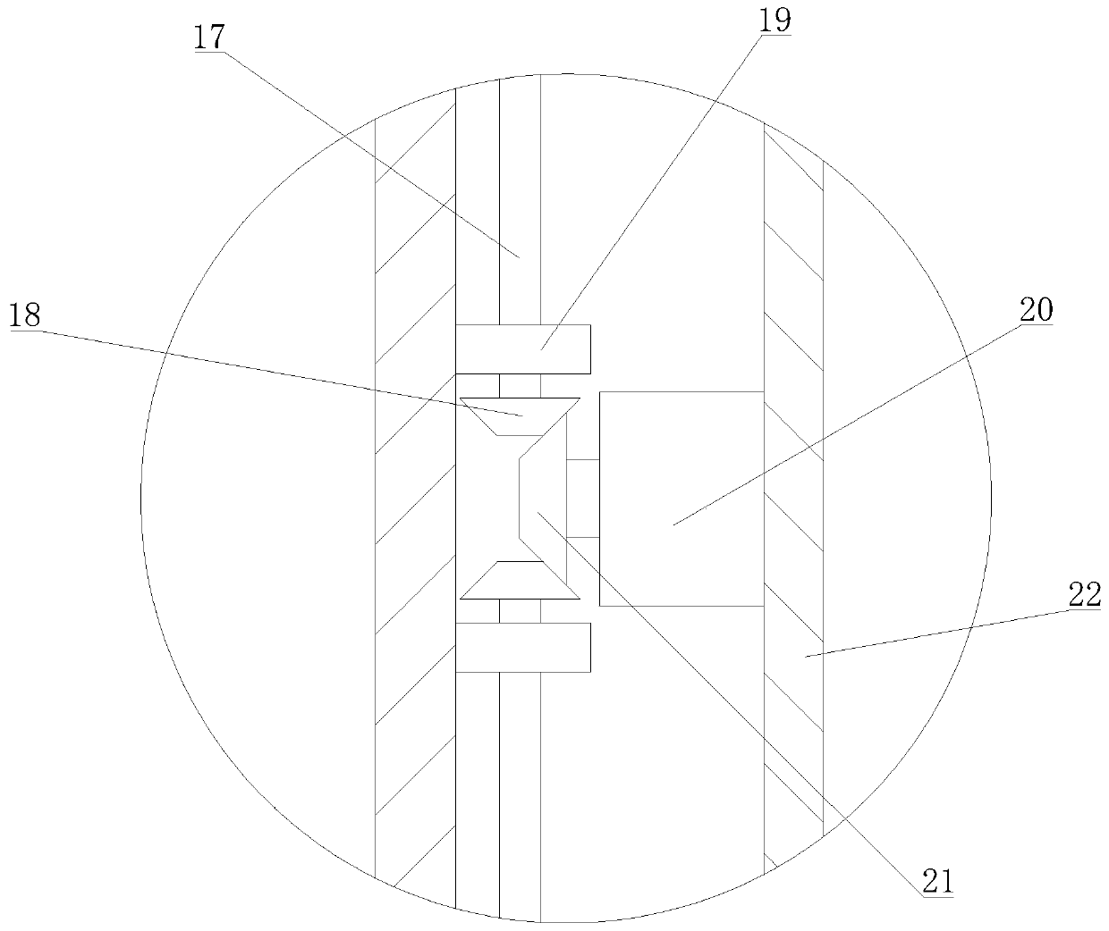
[0027] see Figure 1-7 As shown, a strong heat dissipation type high-voltage switchgear and its working method include a switchgear outer cabinet body 1, a switchgear door 4, a bottom bracket 7, a top bracket 8, a sealing fixing seat 9, a sealing rotating seat 10, a first partition Plate 22, second partition 23, heat dissipation fan 24 and inner cabinet body 29; the bottom of the outer cabinet body 1 of the switch cabinet is provided with several sets of supporting legs, and the upper and lower ends of the outer cabinet body...


PUM


Abstract

The invention discloses a strong heat dissipation type high-voltage switch cabinet and a working method thereof. The strong heat dissipation type high-voltage switch cabinet comprises a switch cabinetouter cabinet body, a switch cabinet door, a bottom support, a top support, a sealing fixed base, a sealing rotating base, a first partition plate, a second partition plate, a heat dissipation fan and an inner cabinet body. A plurality of groups of supporting legs are arranged at the bottom of the switch cabinet outer cabinet body; the upper end and the lower end of the switch cabinet outer cabinet body are respectively provided with a top heat dissipation port and a bottom heat dissipation port. The left end and the right end of the switch cabinet outer cabinet body are respectively providedwith a side heat dissipation port. The switch cabinet door is rotatably connected to the front end of the switch cabinet outer cabinet body. The switch cabinet door is provided with a door handle anda switch lock. The upper and lower end heat dissipation ports are driven to be opened and closed at the same time through a set of motors, driving energy consumption is reduced, the heat dissipationeffect is ensured, the upper and lower end heat dissipation ports are opened and closed according to needs, heat dissipation and moisture prevention of the switch cabinet are effectively achieved, water cooling heat dissipation is conducted while air cooling heat dissipation is conducted, and the super-strong heat dissipation effect of the switch cabinet is achieved.

Description

technical field [0001] The invention relates to the technical field of high-voltage switchgear, in particular to a high-voltage switchgear with strong heat dissipation and a working method thereof. Background technique [0002] The main function of the switchgear is to open and close, control and protect electrical equipment during the process of power generation, transmission, distribution and power conversion in the power system. The components in the switch cabinet are mainly composed of circuit breakers, disconnectors, load switches, operating mechanisms, transformers and various protection devices. [0003] The prior art has disclosed application number 201010263476.6, a heat sink for a circuit board, including a heat sink; the heat sink includes a heat sink bracket, a fan, a heat sink cover, a radiator, and fixing screws; the radiator and the fan connected to each other and installed together on the cooling device bracket; the bottom of the cooling device bracket is p...

Claims


Application Information

Patent Timeline
IPC IPC(8): H02B1/56H02B1/30H02B1/28
CPCH02B1/28H02B1/30H02B1/565
Inventor 张合生平亚玲
Owner ANHUI WANHUA ELECTRICAL TECHNOLOGY CO LTD
Why Eureka
Try Eureka