Distraction hook in lumbar surgery
A technique for surgery and lumbar spine, which is applied in the field of lumbar spine surgery assistance, and can solve problems affecting patients' functional exercise and rehabilitation, distractor shaking, and affecting doctors' surgical sight, etc.
- Summary
- Abstract
- Description
- Claims
- Application Information
AI Technical Summary
Problems solved by technology
Method used
Image
Examples
Embodiment 1
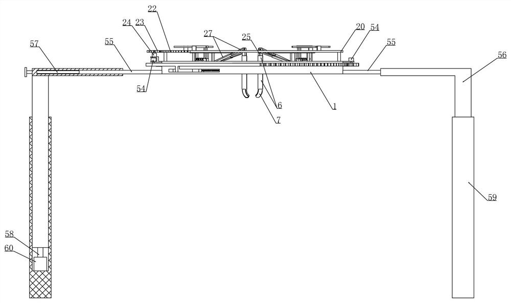
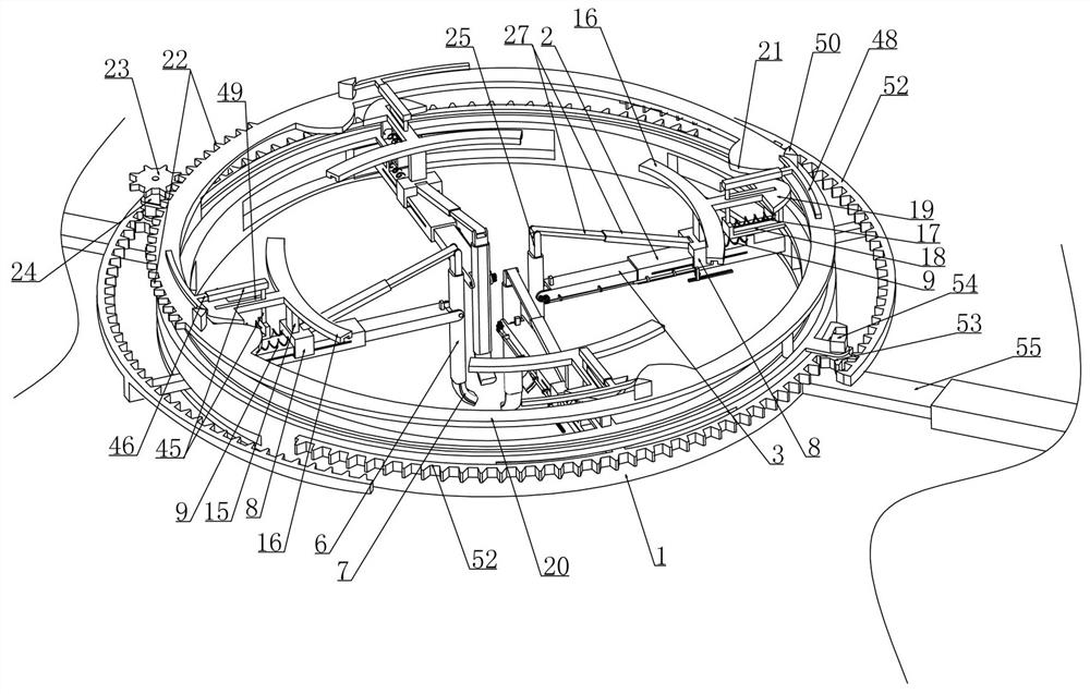
[0045] Embodiment 1, this embodiment provides a kind of distracting hook in lumbar surgery, refer to the attached figure 2 As shown, including the bearing ring 1, it is characterized in that, on the inner surface of the bearing ring 1, we set four bearing cylinders 2 extending radially along the bearing ring 1 around the inner surface of the bearing ring 1, and the bearing cylinders 2 and the bearing ring 1 The inner circular surface is rotated and fitted, and a moving rod 3 is slidably installed in the bearing cylinder 2. The moving rod 3 is driven by a stretching device arranged in the bearing cylinder 2. Refer to the attached Figure 8 , 10 As shown, the spreading device includes a spreading screw 5 threadedly fitted with the moving rod 3 and the spreading screw 5 is driven by a spreading motor 4 installed in the bearing cylinder 2, and the spreading motor 4 drives the spreading screw 5 Rotate and then realize the sliding of the control moving rod 3 along the bearing cyli...
Embodiment 2
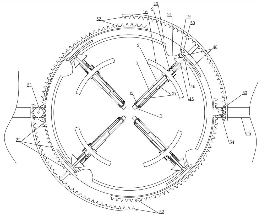
[0052] Embodiment 2, on the basis of embodiment 1, with reference to appended Figure 5 As shown, the U-shaped block 8 is slidably installed on the two side walls of the bearing cylinder 2 and the upper end surface of the U-shaped block 8 is fixedly equipped with an arc-shaped rod 15 coaxial with the bearing ring 1, and the upper end surface of the arc-shaped rod 15 is The arc-shaped guide rail 16 that is coaxially arranged with the bearing ring 1 is installed in rotation fit, and four rectangular plates 18 radially extending along the bearing ring 1 are fixedly installed on the inner surface of the bearing ring 1 at equidistant intervals. The guide slide is installed on the rectangular plate 18. When we need a plurality of second push rods 7 to rotate around the corresponding moving rod 3 to increase the stretching area of the deep abdominal tissue, at this time, we pass The driving device acts on the arc-shaped extrusion plate 19 and forces the arc-shaped extrusion plate 1...
Embodiment 3
[0054] Embodiment 3, on the basis of embodiment 2, with reference to appended Figure 20 As shown, the drive device includes a drive ring 20 that is rotatably mounted on the upper end surface of the bearing ring 1 and coaxially arranged with the bearing ring 1. When we set it up, we fixedly install support rings on both sides of the lower end surface of the drive ring 20 in the axial direction. And on the upper end surface of the bearing ring 1, there is a circular groove (not labeled) that is installed in rotation with the support rod, so that the drive ring 20 can be rotatably installed on the upper end surface of the bearing ring 1. The arc-shaped trigger plate 21 matched with the arc-shaped extruding plate 19 is arranged around equidistantly at intervals, referring to the attached figure 2 As shown, in the initial state, the relative position of the driving ring 20 and the bearing ring 1 is as attached figure 2 As shown in , that is, the arc-shaped trigger plate 21 and ...
PUM
 Abstract
Description
Claims
Application Information
 - R&D
- Intellectual Property
- Life Sciences
- Materials
- Tech Scout
- Unparalleled Data Quality
- Higher Quality Content
- 60% Fewer Hallucinations
Browse by: Latest US Patents, China's latest patents, Technical Efficacy Thesaurus, Application Domain, Technology Topic, Popular Technical Reports.
© 2025 PatSnap. All rights reserved.Legal|Privacy policy|Modern Slavery Act Transparency Statement|Sitemap|About US| Contact US: help@patsnap.com


