Surface treatment device for textile fabrics

A technology of surface treatment device and exhaust gas treatment device, which is applied in the direction of ultrasonic/sonic fiber treatment, dispersed particle separation, chemical instruments and methods, etc., and can solve the problems of inconsistent spacing of textile discharge tubes, inconsistent treatment of textiles, poor consistency of textiles, etc. problems, to achieve the effect of ensuring color fastness, avoiding excessive temperature, and avoiding temperature rise

Pending Publication Date: 2020-09-01
天泓环境科技有限责任公司
View PDF0 Cites 1 Cited by
  • Summary
  • Abstract
  • Description
  • Claims
  • Application Information

AI Technical Summary

Problems solved by technology

The existing plasma treatment equipment has the following technical problems in the process of using functions: 1) Ozone will be generated during the process of treating textiles, and the direct discharge of ozone into the air will pollute the air; 2) Due to the softness of textile materials , it is easy to appear the problem of concave in the middle under the action of gravity, resulting in inconsistent spacing between the textile and the discharge tubes on both sides, which in turn leads to inconsistent treatment on both sides of the textile, making the consistency of the textile poor

Method used


Image

  • Surface treatment device for textile fabrics
  • Surface treatment device for textile fabrics
  • Surface treatment device for textile fabrics

Examples


Embodiment Construction

[0035] Figure 1~11 It is the best embodiment of the present invention, below in conjunction with attached Figure 1~11 The present invention will be further described.

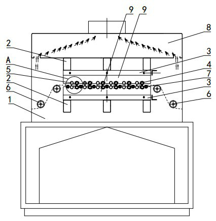
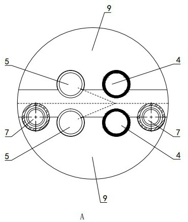
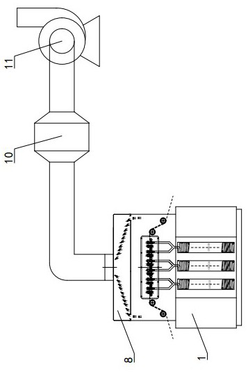
[0036] A textile surface treatment device, including a discharge tube 4, an air guide tube 5, a positioning shaft 7 and a waste gas treatment device, the discharge tubes 4 are arranged in pairs, and the paired two discharge tubes 4 are arranged in parallel and at intervals, and each discharge tube 4 The input side of the textile fabrics is provided with an air guide tube 5, and the side of the air guide tube 5 close to the corresponding discharge tube 4 is provided with an air injection port 501, and the paired two discharge tubes 4 are connected to the power supply, and the waste gas treatment device is arranged in the discharge tube 4. On the upper side of the tube 4, the positioning shaft 7 is provided with a positioning part parallel to the discharge tube 4, the positioning part is located in the middle ...


PUM


Abstract

The invention discloses a surface treatment device for textile fabrics and belongs to the technical field of plasma processing equipment. The surface treatment device for textile fabrics is characterized in that discharge tubes (4) are arranged in pairs, the two discharge tubes (4) arranged in pairs are parallel and are arranged in a spaced mode, an air guide pipe (5) is arranged at a textile fabric input side of each discharge tube (4), an air spraying opening (501) is arranged at the side, close to the corresponding discharge tube (4), of the air guide pipe (5), the two discharge tubes (4) arranged in pairs are both connected with a power source, a waste gas treatment device is arranged at the upper side of the discharge tubes (4), a positioning shaft (7) is provided with a positioning portion parallel to the discharge tubes (4), the positioning portion is located in the middle of the discharge tubes (4) arranged in pairs, and roll shafts (6) used for guiding the textile fabrics arearranged on two sides of the discharge tubes (4). The surface treatment device for textile fabrics can prevent ozone from being directly discharged into the air and polluting the environment, and thepositioning shaft guarantees the consistent interval between the textile fabrics and the discharge tubes on two sides, and further guarantees that two sides of the textile fabrics are treated consistently.

Description

technical field [0001] A textile surface treatment device belongs to the technical field of plasma treatment equipment. Background technique [0002] The application of plasma technology in the textile field is a new technology that people have paid close attention to in recent years. In the past, people used vacuum plasma to discharge various textile fabrics. Experiments have proved that after plasma treatment, it can replace the traditional desizing process and improve dyeing. Final color fastness, and can change the feel. The existing plasma treatment equipment has the following technical problems in the process of using functions: 1) Ozone will be generated during the process of treating textiles, and the direct discharge of ozone into the air will pollute the air; 2) Due to the softness of textile materials , it is easy to appear the problem of concave in the middle under the action of gravity, resulting in inconsistent spacing between the textile and the discharge tub...

Claims


Application Information

Patent Timeline
Patent Type & Authority Applications(China)
IPC IPC(8): D06M10/02B01D53/66B01D53/86
CPCB01D53/8675B01D2255/2073D06M10/02
Inventor 周兆瑞侯正奇苗大刚崔建业吕茂峰
Owner 天泓环境科技有限责任公司
Why Eureka
Try Eureka