Dispensing device for semiconductor chip packaging

A chip packaging and glue dispensing device technology, which is applied to the surface coating liquid device, cleaning method and utensils, cleaning methods using tools, etc., can solve problems that easily affect the dispensing effect, and improve the dispensing quality. Good support, improve the effect of stability

Inactive Publication Date: 2020-09-04
顾骏
View PDF0 Cites 6 Cited by
  • Summary
  • Abstract
  • Description
  • Claims
  • Application Information

AI Technical Summary

Problems solved by technology

[0004] Based on the technical problems that most of the traditional chip processing dispensers have relatively simple structures, and if there is dust attached to the chip, it is easy to affect the dispensing effect. The present invention proposes a dispensing device for semiconductor chip packaging.

Method used


Image

  • Dispensing device for semiconductor chip packaging
  • Dispensing device for semiconductor chip packaging
  • Dispensing device for semiconductor chip packaging

Examples


Embodiment 1

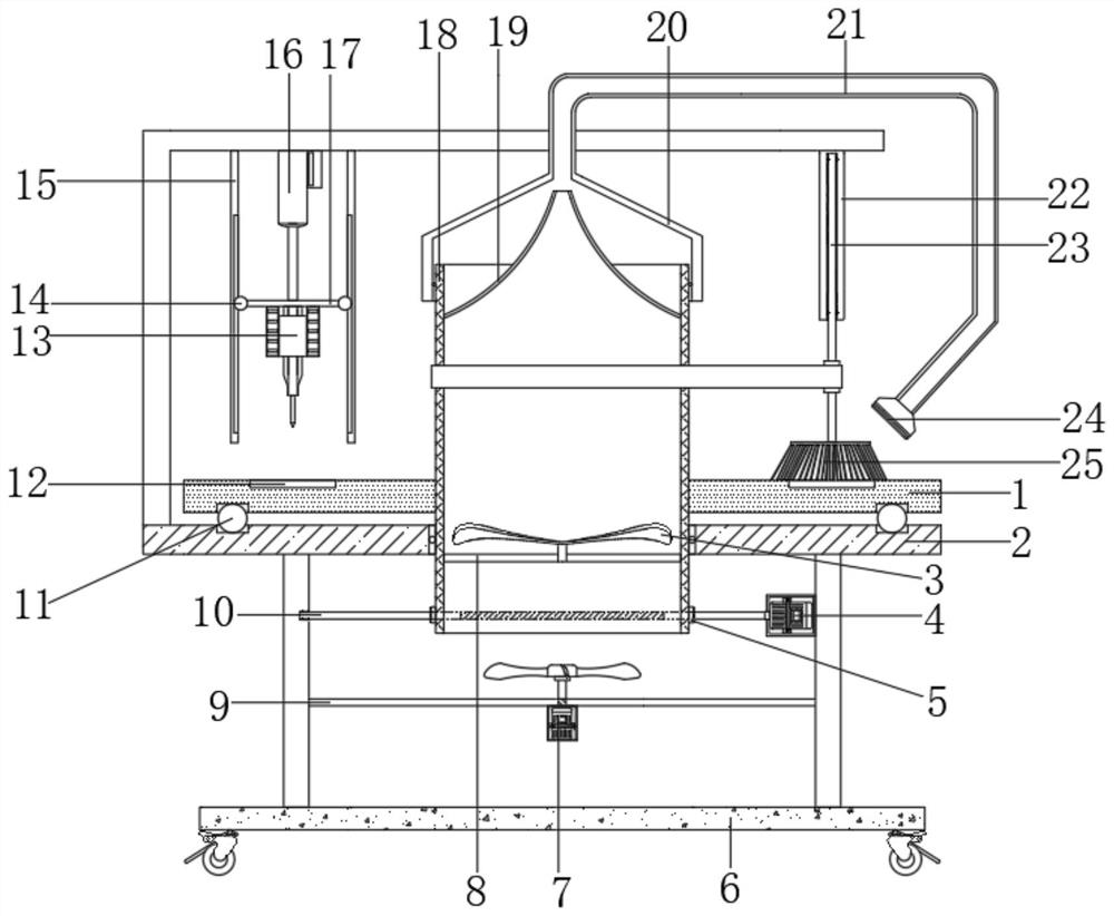
[0030] refer to Figure 1-4 , a dispensing device for semiconductor chip packaging, comprising a dispensing station 1 and a fixed support platform 2, the centers of the dispensing platform 1 and the fixed support platform 2 are respectively provided with a mounting groove and an adapter, and the inner wall of the mounting groove is welded with a The transmission tube 18 connected by the transfer interface through the bearing rotation, and both sides of the bottom outer wall of the fixed support platform 2 are vertically welded with side support plates, and a drive mechanism is installed on the opposite side of the transmission tube 18 and the side support plates, and the side support plates The opposite side is fixed with a bracket 9 by bolts, the bracket 9 is equipped with a blower 7, the top side of the fixed support platform 2 is welded with an L-shaped top plate, and the bottom end side of the end of the top plate is fixed with a fixed tube 22 by bolts. The inner wall of c...

Embodiment 2

[0039] refer to figure 1 and Figure 5 , a dispensing device for semiconductor chip packaging. Compared with Embodiment 1, this embodiment also includes a strengthening mechanism installed on the side of the L-shaped top plate close to the push rod motor 16.

[0040] Wherein, the reinforcement mechanism includes two fixed vertical rods 15 vertically welded to the L-shaped top plate.

[0041] Wherein, the opposite sides of the two fixed poles 15 are provided with arc-shaped inner grooves 26 , and both sides of the mounting plate 17 are welded with sliding ball heads 14 slidably connected with the arc-shaped inner grooves 26 .

[0042] When the present invention is in use: use the setting of the strengthening mechanism, utilize the mutual cooperation between the sliding ball head 14 and the arc-shaped inner groove 26, play a good role in supporting and limiting the mounting plate 17, and then improve the movement of the dispenser 13 up and down. Stability, to ensure the smooth...


PUM


Abstract

The invention belongs to the technical field of chip processing, in particular to a dispensing device for semiconductor chip packaging. In view of the problem that most of the traditional chip processing dispensers are relatively simple in structure and dust attached to the chip affects the dispensing effect easily, the following scheme is proposed. The dispensing device comprises a dispensing platform and a fixed support platform, an installation groove and a transferring opening are respectively formed in the centers of the dispensing platform and the fixed support platform, a transmission cylinder which is rotationally connected with the transferring opening by a bearing is welded on the inner wall of the installation groove, and side support plates are vertically welded at the two sides of the outer wall of the bottom of the fixed support platform. According to the invention, clean air is blown to a chip in a placing groove for dust blowing effect through the action of the transmission cylinder, a fixed cover end and an air pipe and an air filter element; a drive mechanism can drive the transmission cylinder to rotate, a rotating rod and a brush head are driven to rotate by theaction of a belt so as to brush the chip, the effect of removing dust quickly is achieved, and the dispensing quality is improved.

Description

technical field [0001] The invention relates to the technical field of chip processing, in particular to a dispensing device for semiconductor chip packaging. Background technique [0002] A semiconductor chip refers to a semiconductor device that is etched and wired on a semiconductor sheet to achieve a certain function. Not only silicon chips, but also common semiconductor materials such as gallium arsenide and germanium. In order to meet the requirements of mass production, the electrical properties of the semiconductor must be predictable and stable, so the purity of the dopant and the quality of the semiconductor lattice structure must be strictly required. The invention of the semiconductor chip was a pioneering work of the twentieth century that ushered in the information age. [0003] Semiconductor chips need to be dispensing and packaged during processing. For example, the patent document of Chinese patent application No. CN2019204567705 discloses a dispensing dev...

Claims


Application Information

Patent Timeline
Patent Type & Authority Applications(China)
IPC IPC(8): B05C5/02B08B5/02B08B1/00B08B1/04
CPCB05C5/0208B08B1/002B08B1/04B08B5/02
Inventor 顾骏
Owner 顾骏
Why Eureka
Try Eureka