
Battery dispensing curing production line and process

A battery and production line technology, applied in the direction of lead-acid battery, lead-acid battery construction, assembling battery machine, etc., can solve the problems of low energy utilization rate, short transmission and curing stroke, inability to directional heating, etc., to improve the directional utilization rate of heat, Short curing time, adjustable heat intensity

Active Publication Date: 2020-09-04
ZHEJIANG DOULAN INTELLIGENT EQUIP CO LTD
View PDF7 Cites 0 Cited by
  • Summary
  • Abstract
  • Description
  • Claims
  • Application Information

AI Technical Summary

Problems solved by technology

[0005] In view of the above problems, the present invention provides a battery dispensing and curing production line and its technology. By setting the hollow chain plate mechanism to limit the transmission of the battery packs in a joint arrangement, a radiation heating mechanism is set under the hollow chain plate mechanism and a heat reflection mechanism is provided in conjunction with it. After the heat is radiated, it will be reflected upwards and collected on the top cover of the battery pack for directional heating. The high-intensity radiant heating method is used in conjunction with heat reflection and rising blocking settings to achieve concentrated directional heating of heat, high utilization rate, and short transmission and curing strokes. , and cancel the cover-set curing kiln structure, which helps the battery case to maintain normal temperature, simplifies the process, and solves the technical problems of heat dispersion, inability to direct heating, and low energy utilization in the prior art

Method used


Image

  • Battery dispensing curing production line and process
  • Battery dispensing curing production line and process
  • Battery dispensing curing production line and process

Examples


Embodiment 1

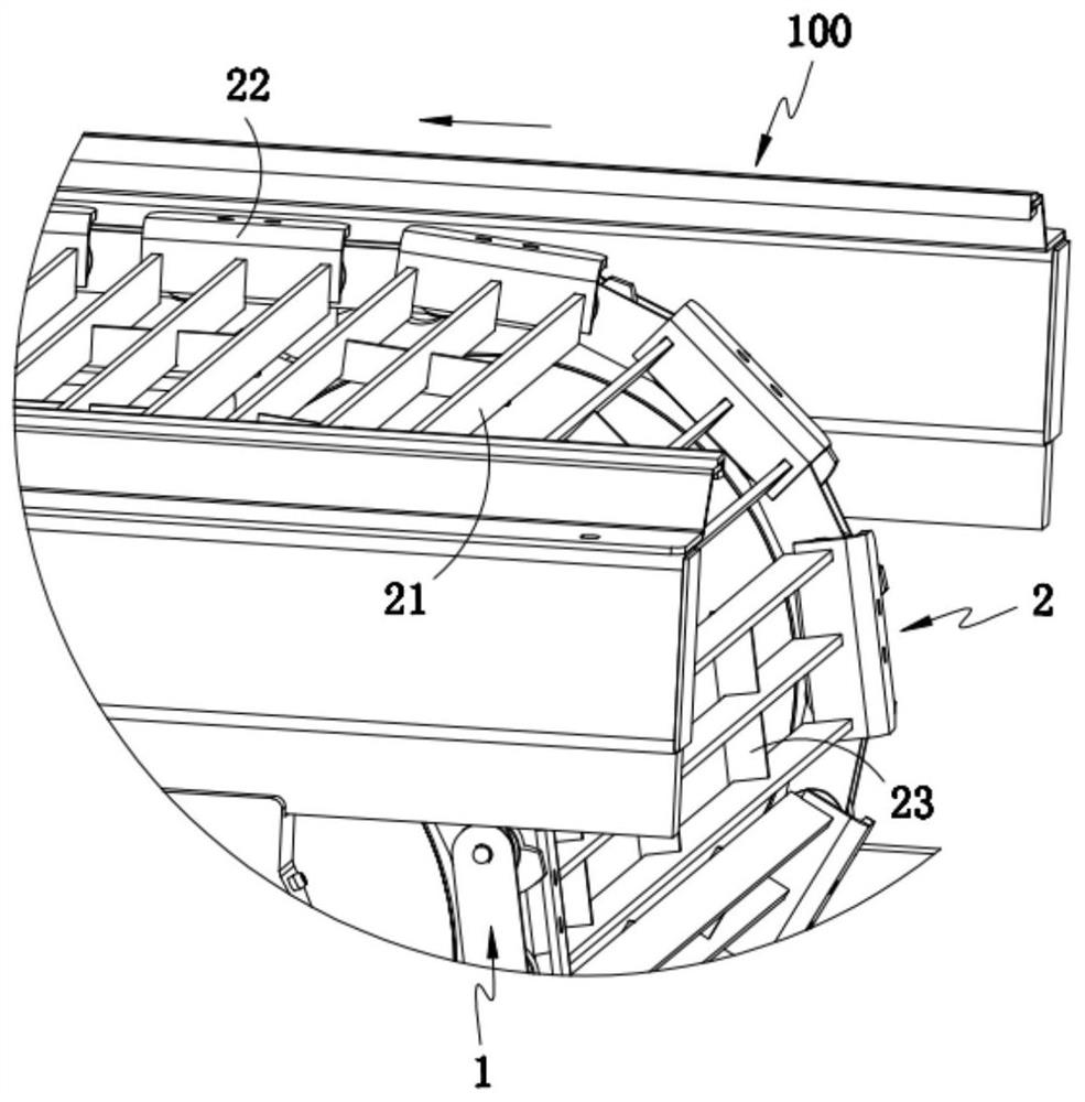
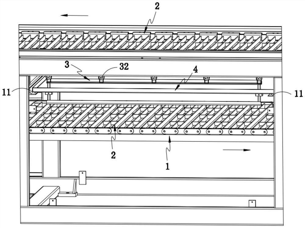
[0041] Such as Figure 1-3As shown, the battery dispensing and curing production line includes a frame 100 and a rotary conveying mechanism 1 installed on the frame 100, and also includes a hollow chain plate mechanism 2 evenly distributed on the rotary conveying mechanism 1, and is arranged on The radiation heating mechanism 3 and the heat reflection mechanism 4 in the middle space of the rotary conveying mechanism 1, such as Figure 4-5 As shown, the battery packs 10 that are glued and arranged one by one are stuck upside down on the hollow chain plate mechanism 2. During the transmission process, the heat radiated outward by the radiation heating mechanism 3 is reflected upward by the heat reflection mechanism 4. And through the hollow chain plate mechanism 2, the dispensing on the cover of the battery pack 10 is heated intensively.

[0042] In this implementation, by setting the hollow chain plate mechanism 2 to limit the transmission of the battery packs 10 that are arra...

Embodiment 2

[0055] For the sake of brevity, only the difference between Embodiment 2 and Embodiment 1 is described below; the difference between Embodiment 2 and Embodiment 1 is:

[0056] Further, such as image 3 As shown, the frame 100 is provided with several slide rails 11 corresponding to each heat reflection mechanism 4, and the bottoms at both ends of the heat reflection mechanism 4 can be erected on the slide rails 11 respectively, and drive the radiation heating Mechanism 3 slides in or out sideways.

[0057] Further, the bracket 31 is vertically penetrated and slidably installed on the heat reflection mechanism 4 , and a lifting adjustment block 30 is arranged on the bracket 31 below the heat reflection mechanism 4 .

[0058] In this embodiment, the radiation heating mechanism 3 and the heat reflection mechanism 4 are set as a one-piece structure. Specifically, the four corners of the bracket 31 penetrate longitudinally and are slidably arranged at the four corners of the botto...

Embodiment 3

[0063] For the sake of brevity, only the differences between Embodiment 3 and Embodiment 1 are described below; the differences between Embodiment 3 and Embodiment 1 are:

[0064] Further, such as figure 1 and Figure 7 As shown, it also includes a transmission overturning mechanism 5 arranged at the transmission end of the rotary conveyor mechanism 1, and the transmission overturning mechanism 5 includes a transmission component 51 transitionally connected with the rotary conveyor mechanism 1 and interlaced with the transmission component 51 The reversing assembly 52, the inverted battery pack 10 is transferred to the transmission assembly 51 and locked in the reversing assembly 52, driven by the reversing assembly 52 to turn over 180° and output in an upright state.

[0065] In this embodiment, by transitionally setting the transmission overturning mechanism 5 at the transmission end of the curing transmission production line, the inverted battery pack 10 after curing can b...


PUM


Abstract

The invention provides a battery dispensing curing production line and process. According to the line, a rack and a rotary conveying mechanism mounted on the rack are included, a hollowed-out chain plate mechanism which is uniformly distributed on the rotary conveying mechanism, a radiation heating mechanism and a heat reflection mechanism are further included, wherein the radiation heating mechanism and the heat reflection mechanism are arranged in the middle space of the rotary conveying mechanism. Battery packs which are arranged in an attached mode are limited and conveyed by arranging thehollowed-out chain plate mechanism, the radiation heating mechanism is arranged below the hollowed-out chain plate mechanism, the heat reflection mechanism is arranged in a matched mode, radiated heat may be reflected upwards and collected on upper cover planes of the battery packs for directional heating, a radiation heating mode with a large intensity is matched with heat reflection and ascending blocking setting, heat concentration directional heating is realized, the utilization rate is high, a conveying curing stroke is short, a covering-set curing kiln structure is omitted, so that battery shells can be kept at a normal temperature, working procedures are simplified, and the technical problem that in the prior art, heat dispersion exists, directional heating is impossible, and the energy utilization rate is low are solved.

Description

technical field [0001] The invention relates to the field of battery production, in particular to a battery dispensing and curing production line and a process thereof. Background technique [0002] Battery, also called lead-acid battery, is a commonly used product in daily life. It converts electrical energy into chemical energy storage through charging, and converts the stored chemical energy into electrical energy again when needed. In the battery production process, the battery needs to be sealed with red and blue glue on the positive and negative poles after the battery is sealed. After the glue is applied, it needs to be heated to dry and cure the resin glue. [0003] The Chinese invention patent with the application number CN201721301803.6 discloses the heating system of the battery resin drying kiln, including a conveyor chain plate, which passes through the drying and curing kiln, and a steam heating tube with an opening facing upward is provided at the bottom of th...

Claims


Application Information

Patent Timeline
Patent Type & Authority Applications(China)
IPC IPC(8): B05C9/14B05C13/02B05D3/02H01M10/04H01M10/12
CPCB05C9/14B05C13/02B05D3/0263H01M10/0404H01M10/12Y02E60/10Y02P70/50
Inventor 钱顺荣梁电钱梦飞赵月康
Owner ZHEJIANG DOULAN INTELLIGENT EQUIP CO LTD
Learn More