Equipment for efficiently removing COD in breeding wastewater
A high-efficiency technology for aquaculture wastewater, applied in animal husbandry wastewater treatment, water pollutants, water/sewage treatment, etc., can solve problems such as uneven discharge of COD remover, reduced utilization rate of COD remover, and low sewage treatment efficiency. , to achieve the effect of improving the efficiency of sewage treatment, improving the stirring effect and improving the utilization rate
- Summary
- Abstract
- Description
- Claims
- Application Information
AI Technical Summary
Problems solved by technology
Method used
Image
Examples
Embodiment 1
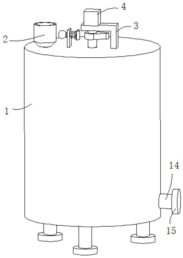
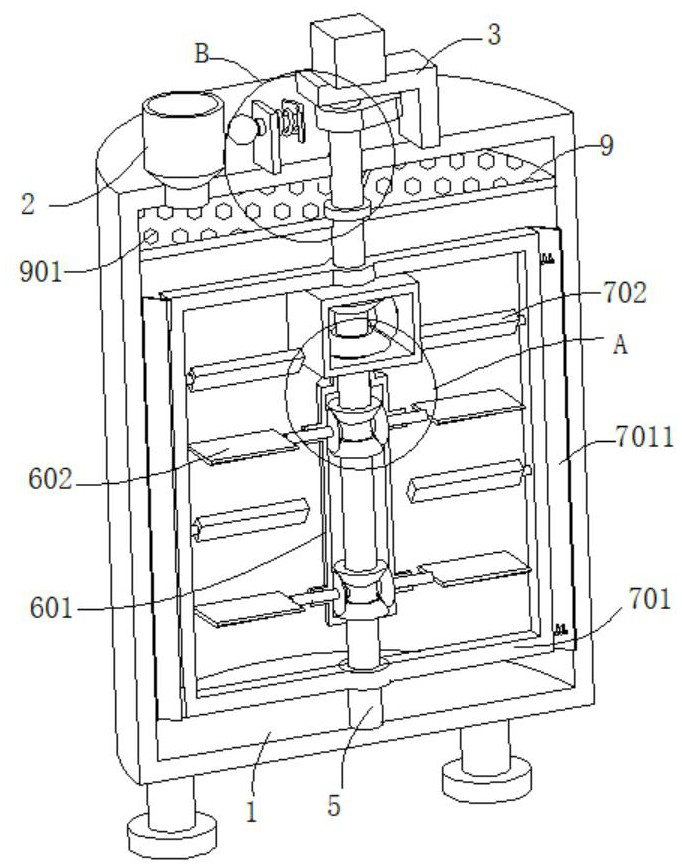
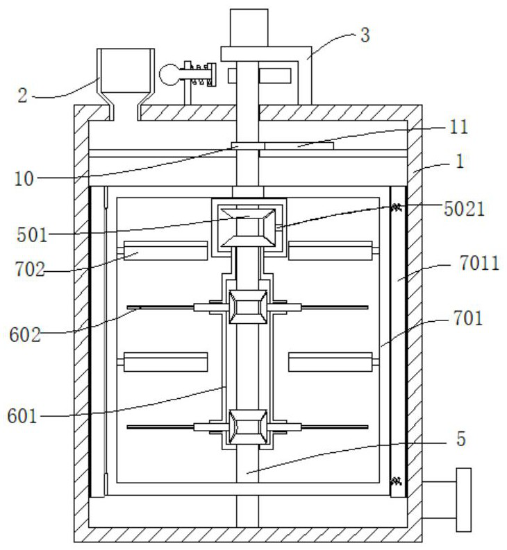
[0038] refer to Figure 1-5, a high-efficiency COD removal device in aquaculture wastewater, comprising a tank body 1, the top of the tank body 1 is connected with a feed port 2, the feed port 2 is set in a bucket shape, the top of the tank body 1 is connected with a support seat 3, the support seat The top of 3 is connected with motor 4, and the output end of motor 4 is connected with rotating shaft, and the end of rotating shaft away from motor 4 passes through support seat 3 and is connected with rotating shaft 5, and the outer wall of rotating shaft 5 is connected with two first fixing rings 7, two An outer frame 701 is connected between the two first fixed rings 7, the outer wall of the outer frame 701 is connected with an outer stirring blade 702, the outer wall of the rotating shaft 5 is connected with a first bevel gear 501, and the outer wall of the rotating shaft 5 is also connected with a sealing box through the first bearing body 502, the first bevel gear 501 is ro...
Embodiment 2
[0041] refer to figure 1 , figure 2 , image 3 , Figure 5 with Figure 8 A high-efficiency removal device for COD in aquaculture wastewater is basically the same as in Example 1. Further, a high-efficiency COD removal device in aquaculture wastewater includes a tank body 1, and a feed inlet 2 is connected to the top of the tank body 1. The feed inlet 2 is set in a bucket shape, the top of the tank body 1 is connected with a support base 3, the top of the support base 3 is connected with a motor 4, the output end of the motor 4 is connected with a rotating shaft, and the end of the rotating shaft away from the motor 4 passes through the support base 3 And be connected with rotating shaft 5, the outer wall of rotating shaft 5 is connected with two first fixed rings 7, is connected with outer frame 701 between two first fixed rings 7, outer wall of outer frame 701 is connected with outer stirring blade 702, rotating shaft 5 The outer wall is connected with a first bevel gea...
Embodiment 3
[0044] refer to figure 1 , figure 2 , image 3 , Figure 4 , Image 6 with Figure 7 , a high-efficiency removal device for COD in aquaculture wastewater, which is basically the same as in Example 1. Further, the rotating shaft 5 is rotatably connected in the hollow pipe body 601, and the outer wall of the rotating shaft 5 is connected with a fourth bevel gear 504. The hollow pipe body The outer wall of 601 is connected with a connecting pipe 6011, and the inner wall of the connecting pipe 6011 is rotatably connected with a rotating rod 6012. The rotating rod 6012 is fixedly connected with the inner stirring blade 602, and the end of the rotating rod 6012 far away from the inner stirring blade 602 is connected with the fourth bevel gear 504. Engaged fifth bevel gear 6013, the outer wall of the rotating shaft 5 is also connected with the sixth bevel gear 8, the sixth bevel gear 8 is placed under the fourth bevel gear 504, and the sixth bevel gear 8 is connected with the fo...
PUM
 Abstract
Description
Claims
Application Information
 - R&D
- Intellectual Property
- Life Sciences
- Materials
- Tech Scout
- Unparalleled Data Quality
- Higher Quality Content
- 60% Fewer Hallucinations
Browse by: Latest US Patents, China's latest patents, Technical Efficacy Thesaurus, Application Domain, Technology Topic, Popular Technical Reports.
© 2025 PatSnap. All rights reserved.Legal|Privacy policy|Modern Slavery Act Transparency Statement|Sitemap|About US| Contact US: help@patsnap.com


