Tube-fin type hard rock tunneling machine

A hard rock roadheader and segment technology, which is applied in the direction of shaft lining, tunnel lining, underground chamber, etc., can solve the problem of waste of resources, etc., and achieve the effect of small environmental impact, high resource utilization rate, and less cutting volume of hard rock

Pending Publication Date: 2020-09-04
CORNELIUS
View PDF0 Cites 0 Cited by
  • Summary
  • Abstract
  • Description
  • Claims
  • Application Information

AI Technical Summary

Problems solved by technology

[0006] Aiming at the above-mentioned problems of the existing tunneling technology, the present invention provides a segment-type hard rock tunneling machine, which is used to make the hard rock in the excavation engineering space into a hard rock segment, and the hard rock segment is reinforced into a composite material tube Segments are used for excavation space lining to save the investment in purchasing segments; the remaining segments are directly sold or enhanced as hard rock composite segments for sale, and the expenditures for cutting the existing excavation technology hard rock resources into construction waste discharge are transformed into hard rock composites of the present invention. The income from the sales of segments made of resources solves the problem of waste of resources in existing technologies

Method used


Image

  • Tube-fin type hard rock tunneling machine
  • Tube-fin type hard rock tunneling machine
  • Tube-fin type hard rock tunneling machine

Examples


Embodiment Construction

[0044] The present invention is further described with reference to accompanying drawing:

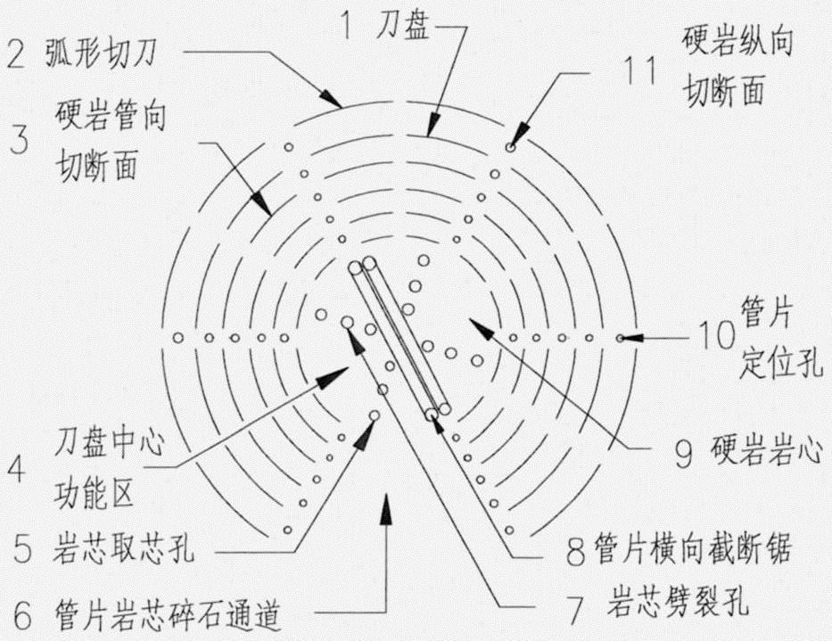
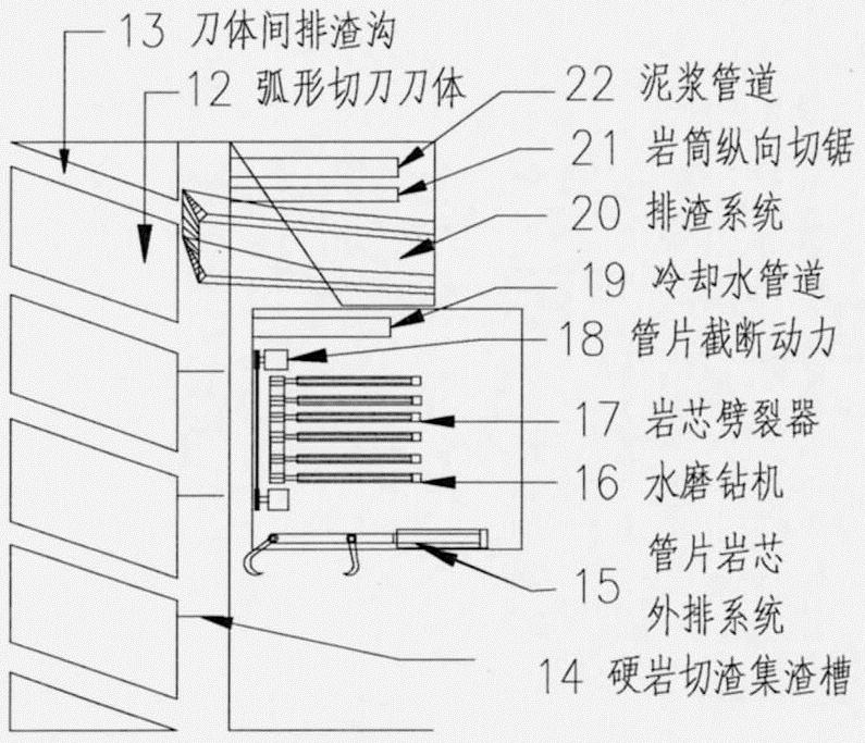
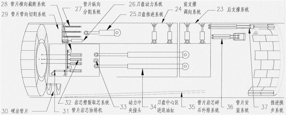
[0045] A tube-type hard rock tunneling machine of the present invention comprises: 1 cutter head, 2 arc-shaped cutters, 3 hard rock pipe-directed cutting surfaces, 4 cutter head central functional areas, 5 core rock core holes, and 6 tube schist cores Gravel channel, 7 core rock splitting holes, 8 segment transverse cutting saws, 9 hard rock cores, 10 segment positioning holes, 11 hard rock longitudinal section, 12 arc cutter body, 13 slag discharge between cutter bodies ditch, 14 hard rock slag cutting slag collection tank, 15 tube schist core discharge system, 16 water mill drilling rig, 17 core rock splitter, 18 segment cutting power, 19 cooling water pipeline, 20 slag discharge system, 21 rock tube longitudinal cutting Saw, 22 mud pipeline, 23 support protection system, 24 direction adjustment and step change system, 25 cutter head propulsion system, 26 cutter head rotation system, ...


PUM


Abstract

The invention relates to a tube-fin type hard rock tunneling machine, belongs to the field of engineering machinery, and is used for solving the problems that according to an existing tunneling technology, the hard rock cutting amount is large, the resources are wasted, the tunneling speed is slow, the tunneling cost is high, concrete pipe sheets are purchased, and the service life of a building is only 100 years. A tunneling technology of the tube-fin type hard rock tunneling machine provided by the invention comprises: a plurality of arc-shaped cutters at the front end of a cutter disc circumferentially cut hard rock in a tunneling space into rock barrels; rock cores are taken out through water milling drills and a splitter in the center of the cutter disk; the rock barrels are cut and sawn into pipe sheets along the longitudinal direction; the pipe sheets and rock bodies are horizontally separated through cut saws in front of the center of the cutter disc; and a feeding and discharging channel at the rear end of the cutter disk is used for feeding cooling cement pastes and discharging the pipe sheets and crushed rocks. Compared with the prior art, according to the tube-fin typehard rock tunneling machine provided by the invention, the tunneling space hard rocks are manufactured into reinforced composite pipe sheets for lining tunneling rock walls, remained pipe sheets are directly sold or increase export revenue to offset the investment, the hard rock cutting amount is small, the resource utilization rate is high, the tunneling speed is fast, the tunneling cost is low,the project investment is low, and the service life of the building can reach to 1000 years.

Description

technical field [0001] The invention relates to a segment type hard rock tunneling machine, which belongs to the technical field of engineering machinery. Background technique [0002] Advantages of existing hard rock excavation technology: Full-face hard rock tunnel boring machine (TBM) is a highly automated equipment integrating machinery, electronics, hydraulic pressure, laser, control and other technologies, which can simultaneously realize equipment propulsion, hard rock crushing, rock slag Discharging, supporting and installing segments, etc., has the advantages of one-time construction, is not affected by the external climate, and reduces the impact on ground buildings and traffic. The mechanical equipment with the most development potential. [0003] Technical problems of existing hard rock excavation engineering: (1) waste of resources: existing hard rock excavation cannot utilize the high-quality hard rock that has formed the earth’s crust for billions of years, a...

Claims


Application Information

Patent Timeline
IPC IPC(8): E21D9/10E21D9/11E21D9/12E21D11/00E21D11/38
CPCE21D9/10E21D9/11E21D9/12E21D11/006E21D11/38
Inventor 康富
Owner CORNELIUS
Why Eureka
Try Eureka