Inserting type modular steel structure connecting joint with reset function

A technology for connecting nodes and steel structures, applied in building components, building structures, protective buildings/shelters, etc., can solve the problems of large damage at the intersection of beams and columns, weak seismic performance, large residual deformation, etc., and achieve high Construction accuracy, reliable performance and good stability

Active Publication Date: 2020-09-08
BEIJING JIAOTONG UNIV
5 Cites 13 Cited by

AI-Extracted Technical Summary

Problems solved by technology

[0004] In order to solve the problems of weak seismic performance of the existing modular steel structure connection nodes, large damage at the intersection of beams and columns after loading, low...

Method used

Cross-type pin connector 7 comprises horizontal plate 7-II, 2 cross-shaped pins 7-I welded in the center of horizontal plate 7-II top surface, and 2 crosses welded in the center of horizontal plate 7-II bottom surface Type latch 7-I, its structural schematic diagram is shown in Figure 3. The cross pins 7-Ⅰ are respectively inserted into the square holes at the ends of the upper box-section modular column 1 and the lower box-section modular column 4 to ensure fast and accurate installation and provide a certain shear resistance. The number of cross pins depends on Depending on the number of modular units, the size depends on the size of the square hole in the box-section module column section; The edge and the upper flange of the lower I-shaped cross-section module beam 5 and the lower groove-shaped cross-section module beam 6 are connected by high-strength bolts 10 .
Self-resetting armpit support 11 comprises inner tube 11-I, outer tube 11-II, disc spring 11-III, disc spring baffle plate 11-IV, inner tube stopper 11-V and outer tube stopper 11-VI , and the specific structure is shown in Figures 4-6. The disc spring is sleeved in the middle of the inner tube, and the two ends are connected with a disc spring baffle that can slide. The inner diameters of the disc spring and the disc spring baffle are slightly larger than the outer diameter of the inner tube. There is a certain distance to ensure the full play of the deformation capacity of the disc spring and the free sliding of the disc spring baffle. The inner tube stopper is welded on the outer side of the inner tube, and the outer tube stopper is welded on the inner side of the outer tube. The inner tube stopper and the disc spring baffle jointly squeeze the disc spring to produce initial compression deformation, and a certain gap is left between the inner tube stopper and the outer tube stopper. Clearance to ensure the relative sliding of the inner and outer tubes. The two ends of the inner tube are welded with cross steel plate 11-Ⅶ to ensure the stability of the self-resetting armpit.
The self-resetting armpit 11 and the box-section module column can also be connected by pull bolts or sleeve devices, and the specific structure and assembly form are shown in Figures 7 to 10. Two pull bolts 16 pass through horizontally respectively. The adjacent box-section modular ...

Abstract

The invention relates to an inserting type modular steel structure connecting joint with a reset function. The inserting type modular steel structure connecting joint comprises a modular steel structure connecting joint body and self-reset haunch supports, wherein the modular steel structure connecting joint body comprises two upper module units, two lower module units, a cross-shaped inserting pin connecting piece, a vertical cover plate, a horizontal cover plate and high-strength bolts, and the four self-reset haunch supports internally provided with disc springs are symmetrically arranged at the corner parts of the joint body and are hinged to module beam columns. According to the inserting type modular steel structure connecting joint, module units are connected through the cross-shaped inserting pin connecting piece, the cover plate and the high-strength bolts, so that it is guaranteed that the joint has enough tensile strength, shear strength and bending strength, a connecting device has no need occupying the use space of a building, the application range is wide, and meanwhile attractiveness is guaranteed; and the arrangement of the self-reset haunch supports can improve thebearing capacity of the joint, delay degradation of the rigidity and strength of the joint, reduce damage to the joint beam-column intersection, avoid premature damage to components, achieve rapid repair and guarantee stability and reliability of the joint performance, and residual deformation after an earthquake is small.

Application Domain

Technology Topic

Flexural rigidityMechanical engineering +7

Image

  • Inserting type modular steel structure connecting joint with reset function
  • Inserting type modular steel structure connecting joint with reset function
  • Inserting type modular steel structure connecting joint with reset function

Examples

  • Experimental program(1)

Example Embodiment

[0033] The present invention will be further described in detail below in conjunction with the drawings.
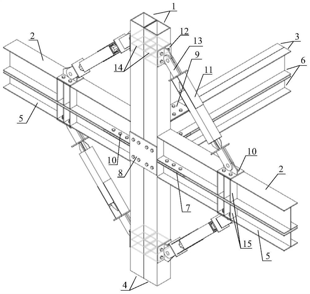
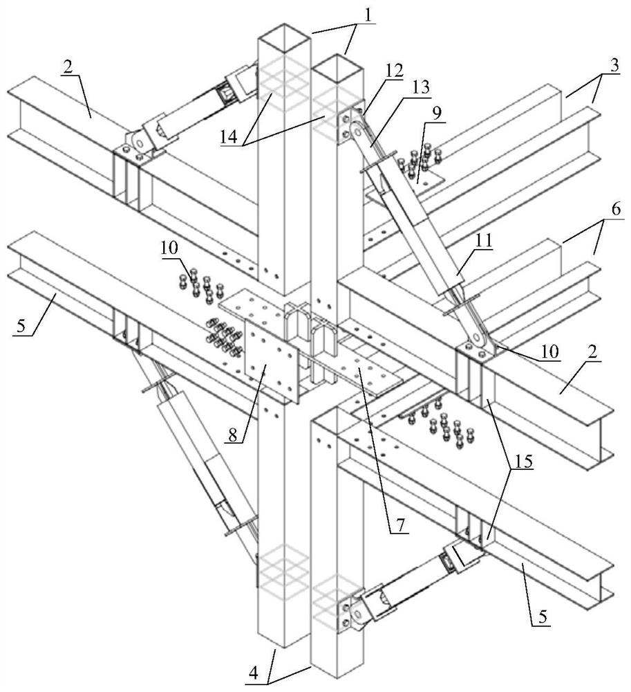
[0034] Such as Figure 1-10 As shown, the plug-in modular steel structure connection node with the reset function includes a modular steel structure connection node and a self-resetting armpit 11. The modular steel structure connection node includes two upper module units, two lower module units, a cross-type plug connector 7, a vertical cover plate 8, a horizontal cover plate 9 and a high-strength bolt 10. The upper module unit includes upper box section module column 1, upper I-section module beam 2, upper channel section module beam 3, upper I-section module beam 2 and upper channel section module beam 3 are welded vertically to the upper box On the adjacent side surface of the end of the module column 1 with section; the lower module unit includes lower box section module column 4, lower I-section module beam 5, lower channel section module beam 6, and lower I-section module beam 5 And the lower trough section module beams 6 are respectively vertically welded on the adjacent side surfaces of the ends of the lower box section module column 4, and the processing of the upper and lower module units is prefabricated in the factory.
[0035] The cross-shaped pin connector 7 includes a horizontal plate 7-Ⅱ, two cross-shaped pins 7-I welded to the center of the top surface of the horizontal plate 7-Ⅱ, and two cross-shaped pins 7 welded to the center of the bottom surface of the horizontal plate 7-Ⅱ -Ⅰ, the structure diagram is as image 3 Shown. Cross-shaped bolt 7-I is inserted into the end square holes of upper box-section module column 1 and lower box-section module column 4 respectively to ensure fast and accurate installation and provide certain shear resistance. The number of cross-shaped bolts depends on For the number of module units, the size depends on the size of the square hole of the box section module column section; the overhanging part of the horizontal plate 7-Ⅱ and the upper I-shaped section module beam 2, the lower wing of the upper trough section module beam 3 The upper flange and the upper flange of the lower I-shaped cross-section module beam 5 and the lower trough-shaped cross-section module beam 6 are connected by high-strength bolts 10.
[0036] The vertical cover plate 8 is installed on the flange ends of the upper box-section modular column 1 and the lower box-section modular column 4 by high-strength bolts 10, and is used to strengthen the lower flange and the lower box-shape of the upper box-section modular column 1 Connection of section module column 4. The horizontal cover plate 9 is installed on the flanges of adjacent trough-section module beams by high-strength bolts 10 to strengthen the connection of adjacent trough-section module beams.
[0037] The self-resetting armrest 11 includes an inner tube 11-Ⅰ, an outer tube 11-Ⅱ, a disc spring 11-Ⅲ, a disc spring baffle 11-Ⅳ, an inner tube stopper 11-Ⅴ and an outer tube stopper 11-VI. Specific structure Such as Figure 4~6 Shown. The disc spring is sleeved in the middle of the inner tube, and both ends are connected with a sliding disc spring baffle. The inner diameter of the disc spring and disc spring baffle is slightly larger than the outer diameter of the inner tube. The outer surface of the disc spring and disc spring baffle and the inner surface of the outer tube are both set There is a certain distance to ensure the full play of the deformation capacity of the disc spring and the free sliding of the disc spring baffle. The inner tube stop is welded on the outside of the inner tube, and the outer tube stop is welded on the inner side of the outer tube. The inner tube stop and the disc spring baffle co-extrude the disc spring to produce initial compression deformation, and there is a certain amount between the inner tube stop and the outer tube stop. Clearance to ensure the relative sliding of the inner and outer pipes. Both ends of the inner tube are welded with cross steel plates 11-Ⅶ to ensure the stability of the self-resetting armpit support.
[0038] There are four self-resetting arm supports 11, which are installed symmetrically on the box-section module column (including the upper box-section module column and the lower box-section module column) and the corresponding I-section module beam (including the upper I-section module column). Section module beam and lower I-section module beam); one end of the self-resetting haunch 11 is connected to the flange of the box-section module column through the gusset plate 12, and the other end is connected to the flange of the I-section module beam through the gusset plate 12 The box-section module column and the I-shaped section module beam are respectively provided with column stiffener plates 14 and beam stiffener plates 15 to prevent local buckling. The self-resetting armrest 11 and the box-shaped section module column and the I-shaped section module beam all have an angle of 45°.
[0039] The self-resetting armrest 11 and the box-section module column can also be connected by a pair of tension bolts or sleeve devices. The specific structure and assembly form are as follows Figure 7~10 As shown, two paired bolts 16 horizontally pass through the adjacent box-section module column and the gusset plate 12 on both sides of the box-section module column, and corresponding torque is applied to them to ensure the connection is tight, so that the side arms on both sides are supported The force can be transmitted directly through the tension bolts to reduce the damage of the box-shaped cross-section module column; the sleeve device 17 includes two channel steels with overhanging plates. The sleeve device 17 is horizontally connected to the adjacent box-shaped cross-section module column by the high-strength bolt 10, and the overhanging plate of the sleeve device 17 is directly connected with the pin connector 13 to form a stable force transmission system. The self-resetting armpits on both sides transmit force to each other through the sleeve device 17 and the high-strength bolts to prevent the box-shaped section module column from directly bearing the concentrated force and ensure the stability of the overall component performance.
[0040] The materials of the upper and lower module units, cross-pin connecting plate and cover plate of the plug-in modular connection node with reset function mentioned above are all made of low-alloy high-strength structural steel Q345 steel. The specific size can be selected according to the design requirements. The outer tube of the self-resetting armpit 11 is made of ordinary carbon structural steel Q235 steel, and the inner tube, disc spring baffle, inner tube stopper, outer tube stopper and cross steel plate are all made of low-alloy high-strength structural steel Q345 steel. The spring is made of hot-rolled spring steel, the grade is 60Si2MnA. Column stiffener plates, beam stiffener plates, gusset plates, pin connectors and sleeve devices are all made of low-alloy high-strength structural steel Q345 steel, and the tension bolt 16 adopts the 10.9 grade (22MnTiB) tension bolt, and the high-strength bolt 10 Use 10.9 grade (20MnTiB) bolts.
[0041] The implementation process of the plug-in modular steel structure connection node with the reset function shown in the present invention is as follows: in application, first insert the two upper module units and the two lower module units into the corresponding positions of the cross-shaped pin connector 7 vertically. , And use high-strength bolts 10 to connect the horizontal plate 7-Ⅱ and the adjacent flanges of the upper and lower I-shaped section module beams, determine the installation position of the cover plate, and complete the bolt connection of the cover plate at the flange of the box section module column and the flange of the groove section module beam . In accordance with the requirements of force and deformation, the disc spring 11-Ⅲ of the self-resetting armpit 11 is given initial pre-compression, and the self-resetting armrest 11 is installed symmetrically at a certain position from the core area at the corner of the node, which is combined with the box-section module column, The modular beams of the font section are all at a 45° angle. The self-resetting haunches 11 can be directly connected to the flanges of the box-section module column and the flange of the I-section module beam through the gusset plate, and they can also be pulled together with the box-section module column. Bolt connection or sleeve device connection.
[0042] In normal use, the connecting node and the self-resetting brace 11 jointly bear the vertical load to maintain balance. Under the action of an earthquake, the load is transferred to each other in the four modular units through the cross-shaped bolt connector 7, the vertical cover 8, the horizontal cover 9 and the high-strength bolt 10. At the same time, the box-section module column and the I-section module beam The force is transmitted to the self-resetting armpit 11 through the gusset plate. When the force exceeds the initial preload of the disc spring 11-Ⅲ, the inner tube 11-I and the outer tube 11-II of the self-resetting armpit 11 move relative to each other. The tube stop 11-VI further squeezes the disk spring 11-Ⅲ through the disk spring baffle 11-Ⅳ, causing it to produce greater compression deformation and provide sufficient restoring force. Since the self-resetting armpits on the adjacent two sides are always along When the force is transmitted in a specific direction, the reaction force on the box-section module column and I-section module beam will cancel each other partly, reducing the impact on the box-section module column and I-section module beam; when the load is gradually When it is reduced, the self-resetting armrest 11 plays a role in the non-offsetting part of the reaction force of the box-shaped section module column and the I-shaped section module beam, helping the component to restore to the state before the deformation. The four self-resetting armrests 11 arranged symmetrically work together and can play the same role under tension and compression, avoiding premature failure of module units due to local damage, improving the ductility and bearing capacity of the overall structure, and reducing structural residuals Deformed.
[0043] The above embodiments are only used to illustrate the present invention, but not to limit the present invention. Those of ordinary skill in the relevant technical fields can make various changes and modifications without departing from the essence and scope of the present invention. Therefore, all The equivalent technical solutions also belong to the protection scope of the present invention.
[0044] The content not described in detail in this specification belongs to the prior art known to those skilled in the art.

PUM

no PUM

Description & Claims & Application Information

We can also present the details of the Description, Claims and Application information to help users get a comprehensive understanding of the technical details of the patent, such as background art, summary of invention, brief description of drawings, description of embodiments, and other original content. On the other hand, users can also determine the specific scope of protection of the technology through the list of claims; as well as understand the changes in the life cycle of the technology with the presentation of the patent timeline. Login to view more.

Similar technology patents

Shock absorbing apparatus

InactiveUS6964451B1Easy constructionSuitable for retrofit into existing vehiclePedestrian/occupant safety arrangementElastic dampersEnergy absorbingIn vehicle
Owner:BERGEY KARL H

Classification and recommendation of technical efficacy words

  • Quality improvement
  • Easy construction

Monodisperse core/shell and other complex structured nanocrystals and methods of preparing the same

ActiveUS20050129947A1Narrow size distributionQuality improvementMaterial nanotechnologyFrom normal temperature solutionsChemistrySemiconductor nanostructures
Owner:THE BOARD OF TRUSTEES OF THE UNIV OF ARKANSAS

Hand-held machine tool

Owner:ROBERT BOSCH GMBH
Why Eureka
Try Eureka