Optical orbital angular momentum machine learning recognition method based on turbulence effect

A technology of orbital angular momentum and machine learning, applied in the field of optical communication, can solve problems such as difficult learning, high training difficulty, and a large number of training samples, and achieve the effects of reducing learning difficulty, improving recognition accuracy, and shortening calculation time

Inactive Publication Date: 2020-09-08
XIDIAN UNIV
View PDF4 Cites 7 Cited by
  • Summary
  • Abstract
  • Description
  • Claims
  • Application Information

AI Technical Summary

Problems solved by technology

Although the algorithm seems simple, it is difficult to apply a model to a variety of turbulent environments. Directly using images for orbital angular momentum pattern recognition not only requires a large number of training samples but also is difficult to learn. When the number of orbital angular momentum patterns is large, the accuracy rate will decrease. The calculation time is significantly reduced, and the calculation time is more lengthy, and there are still some problems in the actual optical communication system
[0005] In summary, the problems existing in the existing technology are that the recognition accuracy is not high when large-scale orbital angular momentum and strong turbulence are transmitted over long distances. The recognition method based on machine learning has a large sample size, high training difficulty, and low computational efficiency.

Method used


Image

  • Optical orbital angular momentum machine learning recognition method based on turbulence effect
  • Optical orbital angular momentum machine learning recognition method based on turbulence effect
  • Optical orbital angular momentum machine learning recognition method based on turbulence effect

Examples


Embodiment 1

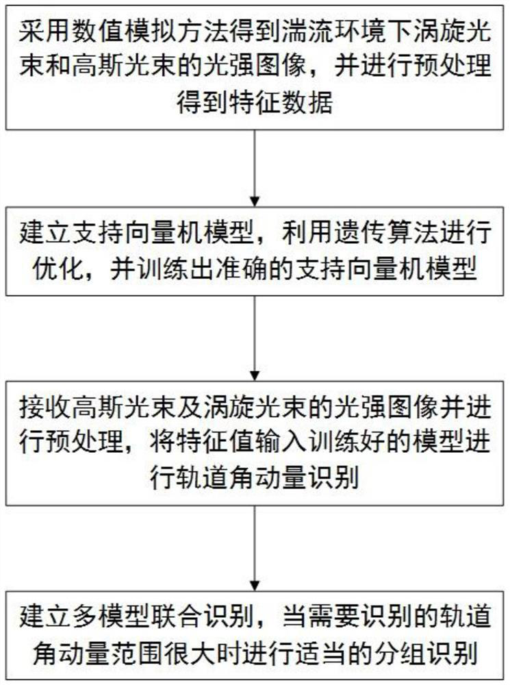
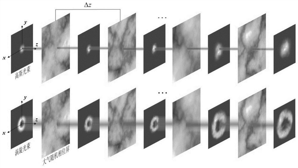
[0028] With the rapid development of optical communication technology, people's demand for information transmission volume and information security continues to increase, and the new degree of freedom of orbital angular momentum provides a new direction for people. Optical communication technology based on orbital angular momentum can greatly improve the information transmission capacity and spectrum utilization of communication, and has great development potential. Free space optical communication uses the atmosphere as a channel, but due to the complexity and randomness of atmospheric turbulence, it will cause mode crosstalk during orbital angular momentum transmission, thus increasing the bit error rate of optical communication systems based on orbital angular momentum. Therefore, the high-precision identification of orbital angular momentum under turbulent transmission of vortex beams is an important link to improve the link performance of optical communication systems. Th...

Embodiment 2

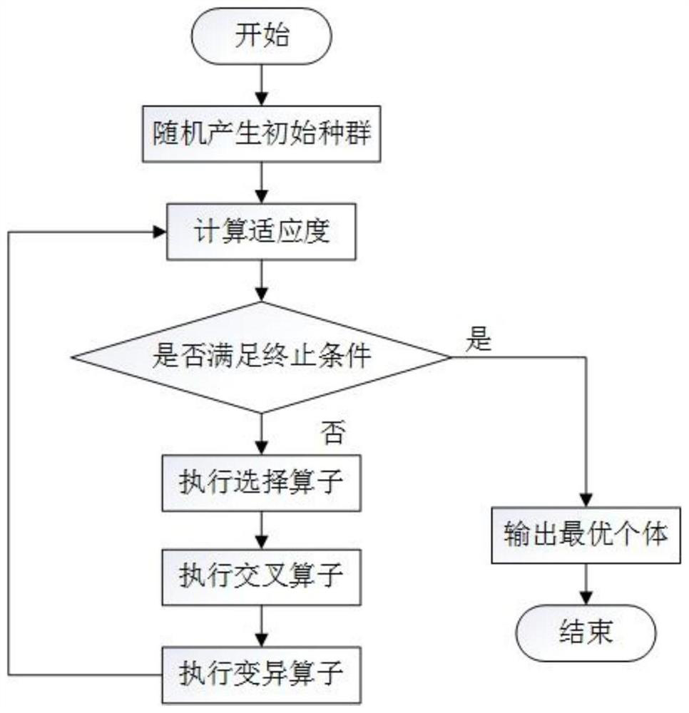
[0041] The optical orbital angular momentum machine learning identification method based on turbulence effect is the same as embodiment 1, adopts genetic algorithm in step 2 and utilizes feature vector to train more optimized support vector machine multi-classification model, specifically comprises the following steps:

[0042] (2a) Build a support vector machine multi-classification model: use the global construction method to construct a classifier to distinguish multi-class samples, and use Lagrangian expansion to obtain a support vector machine multi-classification model:

[0043]

[0044] In the formula, k represents the kth type, k=1,2,3,...,n; w k is the weight vector of the kth type; b k is the offset of the kth type; m=argmax{[(x·w 1 )+b 1 ],…,[(x·w n )+b n ]}, m≠k, x represents multi-class samples a i (i=1,2,3,...,l k ) represents the Lagrangian coefficient; C is the penalty factor; the kernel function K(x i ,x j ) Select the Radial basis kernel function...

Embodiment 3

[0050] The optical orbital angular momentum machine learning recognition method based on the turbulence effect is the same as that in embodiment 1-2, and the establishment of multiple models in step 4 performs group joint recognition of images with a larger recognition range, see Figure 5 , including the following steps:

[0051] (4a) Establish a joint recognition model: when the orbital angular momentum range of the light intensity distribution map to be recognized is large, set the recognition range to (1,2,...,a*b), referred to as the light intensity distribution map with a large recognition range Identify objects for a wide range. Divide the larger recognition range into b consecutive small ranges, namely (1,2,...,a), (a+1,a+2,...,2a),..., ((b-1 )*a+1,(b-1)*a+2,...a*b), referred to as the light intensity distribution map with a small recognition range is a small-range recognition object, where b is the number of small-range recognition objects, a Identify the number of ...


PUM


Abstract

The invention discloses an optical orbital angular momentum machine learning recognition method based on a turbulence effect, and solves the problems that a huge training sample is needed when an existing machine learning method is used for recognizing an orbital angular momentum mode, and synchronous recognition of various turbulence environments is difficult to realize. The method comprises thesteps of obtaining a training sample under a numerical simulation condition; training a support vector machine multi-classification model with more optimized parameters by using a genetic algorithm and the feature vectors; performing orbital angular momentum recognition by using the trained support vector machine multi-classification model; and grouping joint identification is carried out on the images with a large identification range. According to the invention, a physical mechanism and machine learning are combined for optical orbital angular momentum identification. According to the method, the orbital angular momentum mode number of the vortex beam in various atmospheric turbulence environments can be effectively recognized, the accuracy is far higher than that of a traditional optical detection method, compared with a machine learning method based on an image algorithm, training samples can be effectively reduced, and the learning difficulty is lower. The optical orbital angularmomentum machine learning recognition method is used for free space optical communication.

Description

technical field [0001] The invention belongs to the technical field of optical communication, and mainly relates to efficient identification of optical orbital angular momentum, in particular to a turbulent effect-based optical orbital angular momentum machine learning identification method for free-space optical communication based on optical orbital angular momentum. Background technique [0002] With the rapid development of optical information technology, information exchange methods continue to increase, the scope of information continues to expand, people's demand for information transmission, information security and confidentiality continues to increase, which leads to the transmission channel of optical information by optical fiber with limited space The medium extends to the atmosphere and water medium with infinite or semi-infinite space, and the carrier of optical information also adds a new degree of freedom of orbital angular momentum to the traditional degrees ...

Claims


Application Information

Patent Timeline
Patent Type & Authority Applications(China)
IPC IPC(8): G06N20/10G06N3/12G06K9/62
CPCG06N20/10G06N3/126G06F18/2411
Inventor 程明建耿思琦郭立新孙日东李江挺
Owner XIDIAN UNIV
Why Eureka
Try Eureka