
Ridge holing device

A technology of working device and driving device, which is applied in agriculture, planting methods, excavation/covering of trenches, etc. Hole effect, the effect of avoiding soil backflow

Inactive Publication Date: 2020-09-11
FUJIAN YONGSHUN MACHINERY CO LTD
View PDF6 Cites 0 Cited by
  • Summary
  • Abstract
  • Description
  • Claims
  • Application Information

AI Technical Summary

Problems solved by technology

[0002] In agricultural production in arid areas, many crops need to make a deep hole with a diameter of 20-40 cm and a depth of 18-35 cm on the ridge before the seedlings are transplanted, and then mix the fertilizer into the soil at the bottom of the hole, and then put The seedlings are planted in the hole, watered with fixed root water, and finally covered with plastic film. This kind of planting agronomy is to create a relatively stable heat preservation and moisturizing environment for the seedlings after transplanting for a period of time. Therefore, the size and depth of the hole are more particular; manual pond digging is generally done manually with a hoe or shovel to dig out ponds with fixed size intervals, which not only has high cost and low production efficiency, but also Hole size and spacing are not standard
At present, there are also miniature pond making machines. Basically, a pond making machine is attached to the rear of the ordinary micro tillage machine. This layout determines that the operator must control the whole process when the machine is working. Not only is the labor intensity of the machine hand high, but also Moreover, it is difficult to ensure that the pond must be placed in the middle of the ridge, and after the pond is dug out, the soil in the pond cannot be discharged in time, resulting in backfilling of the surrounding soil into the cave, making the puddle small in size, which is not conducive to the growth of young seedlings. transplant
However, the pond-making machine originally invented by our company, due to the unsatisfactory movement track of the pond-making shovel, resulted in an unsatisfactory pond size.

Method used


Image

  • Ridge holing device
  • Ridge holing device

Examples


Embodiment 1

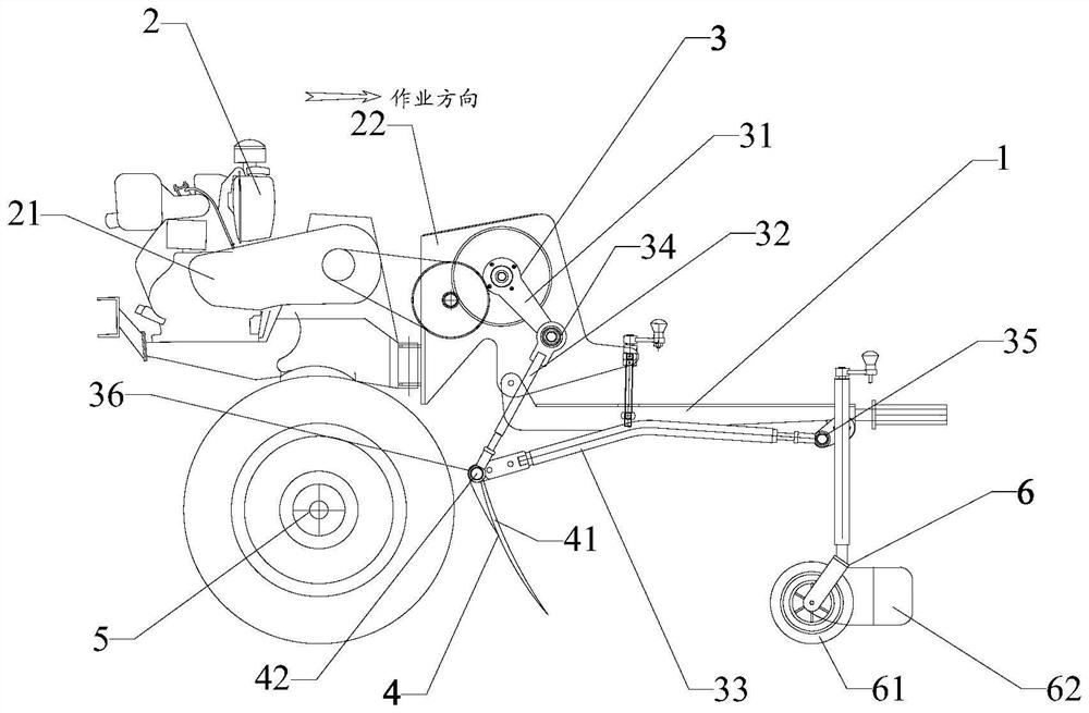
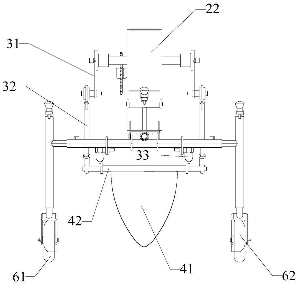
[0043] A ground ridge punching operation device, comprising a frame 1, a driving device 2, a transmission assembly 3, a hole punching shovel mechanism 4 and a driving wheel 5; the driving device 2 is connected to the frame 1, and the driving wheel 5 is connected to Frame 1, the drive wheel 5 is in transmission connection with the drive device 2, and the frame 1 advances along the working direction driven by the drive device 2; the transmission assembly 3 includes a crank 31, a connecting rod 32 and a rocker 33, One end of the crank 31 is in transmission connection with the driving device 2, and the crank 31 rotates under the drive of the driving device 2, and one end of the connecting rod 32 is hinged to the other end of the crank 31 through the first articulated bearing 34; The shovel mechanism 4 is fixedly connected with the connecting rod 32, one end of the rocking lever 33 is hinged to the frame 1 through the second hinged bearing 35, and the other end is hinged to the hole...


PUM


Abstract

The invention relates to the technical field of agricultural machinery, in particular to a ridge holing device. The ridge holing device comprises a rack, a driving device, drive assemblies, a holing shovel mechanism and a drive wheel, wherein cranks are driven by the drive assemblies, so that connecting rods are driven to swing forwards and backwards, and swinging of the connecting rods is limitedby rocking bars; the axial directions of a first hinged bearing, a second hinged bearing and a third hinged bearing are all perpendicular to the operation direction, so that the swinging direction ofthe connecting rods is in the rear downward and front upward direction of the operation direction; the holing shovel mechanism is fixedly connected to the connecting rods, accordingly, the holing shovel mechanism swings in the front, downward, rear and upward directions with the connecting rods, the lower part of the holing shovel mechanism can swing forwards and backwards in a certain range, thus, the length size of a hole can be increased properly and soil in the hole can be sufficiently forwards thrown out, and the holing effect is substantially improved.

Description

technical field [0001] The invention relates to the technical field of agricultural machinery, in particular to a ridge drilling operation device. Background technique [0002] In agricultural production in arid areas, many crops need to make a deep hole with a diameter of 20-40 cm and a depth of 18-35 cm on the ridge before the seedlings are transplanted, and then mix the fertilizer into the soil at the bottom of the hole, and then put The seedlings are planted in the hole, watered with fixed root water, and finally covered with plastic film. This kind of planting agronomy is to create a relatively stable heat preservation and moisturizing environment for the seedlings after transplanting for a period of time. Therefore, the size and depth of the hole are more particular; manual pond digging is generally done manually with a hoe or shovel to dig out ponds with fixed size intervals, which not only has high cost and low production efficiency, but also The hole size and spaci...

Claims


Application Information

Patent Timeline
IPC IPC(8): A01C5/04
CPCA01C5/04
Inventor 张培坤
Owner FUJIAN YONGSHUN MACHINERY CO LTD
Learn More