Swinging type feeding mechanism

A feeding mechanism and swing-type technology, applied in the field of agricultural machinery, can solve problems such as easy accumulation and material blockage, achieve uniform and continuous feeding, prevent accumulation, and increase the flow path

Pending Publication Date: 2020-09-11
HEILONGJIANG PROV AGRI MACHINERY ENG SCI INST +1
View PDF0 Cites 1 Cited by
  • Summary
  • Abstract
  • Description
  • Claims
  • Application Information

AI Technical Summary

Problems solved by technology

[0004] The purpose of the present invention is to solve the problem that corn silage materials wit

Method used


Image

  • Swinging type feeding mechanism
  • Swinging type feeding mechanism
  • Swinging type feeding mechanism

Examples


specific Embodiment approach 1

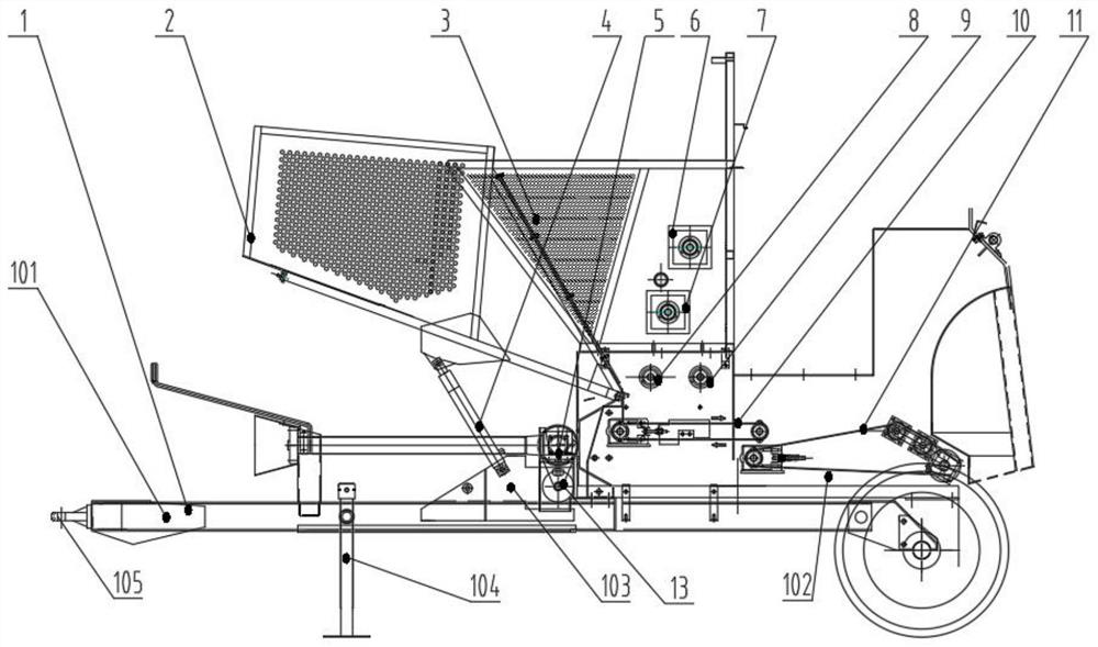
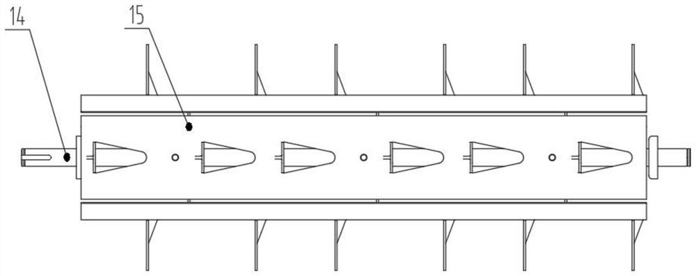
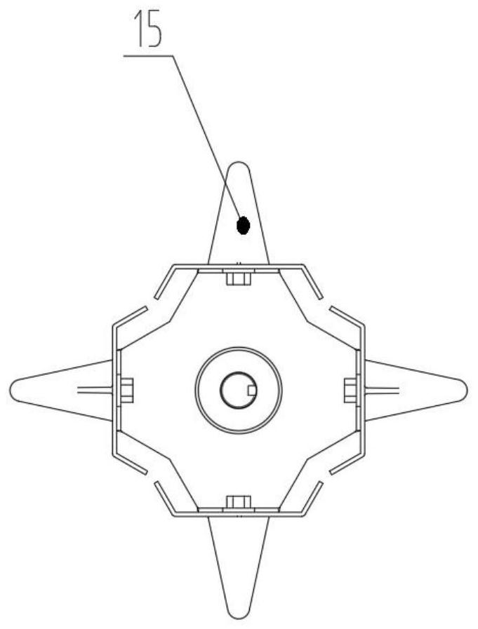
[0030] Specific implementation mode one: combine Figure 1-Figure 5 Describe this embodiment, a kind of swing type feed mechanism of this embodiment, comprise frame 1, swing hopper 2, fixed hopper 3, hydraulic system 5, first material shifting roller 6, second material shifting roller 7, third The material shifting roller 8, the first-level transmission mechanism 10 and the second-level transmission mechanism 11, the frame 1 is fixedly connected with the fixed hopper 3, the swing hopper 2 is hingedly installed on the fixed hopper 3, and the first material removal roller 6 is installed inside the fixed hopper 3 With the second push roller 7, the third push roller 8 is installed inside the fixed hopper 3, the primary transmission mechanism 10 is positioned at the lower side of the fixed hopper 3, and the secondary transmission mechanism 11 is positioned at the right side of the primary transmission mechanism 10. The stage transmission mechanism 11 establishes a connection with t...

specific Embodiment approach 2

[0032] Specific implementation mode two: combination figure 1 Describe this embodiment, a kind of swing type feeding mechanism of this embodiment, frame 1 comprises bottom frame 101, stand 102 and auxiliary stand 103, the two sides of bottom frame 101 are fixedly connected with stand 102 and auxiliary stand respectively symmetrically. The stand 103, the auxiliary stand 103 and the stand 102 are respectively arranged on the left and right sides of the fixed hopper 3, and the secondary transmission mechanism 11 is connected with the stand 102, and the material on the fixed hopper 3 is driven by its own gravity, the first shifting roller 6 and the second feeding roller 7 to convey to the working direction, the first feeding roller 6 and the second feeding roller 7 ensure that the material enters the next process with an appropriate delivery amount, and at the same time prevent material accumulation, arching and blockage.

specific Embodiment approach 3

[0033] Specific implementation mode three: combination figure 1 Describe this embodiment, a kind of oscillating feed mechanism of this embodiment, also comprise the 4th material transfer roller 9, the 4th material transfer roller 9 is connected with fixed hopper 3, the 4th material transfer roller 9 and the 3rd material transfer roller 8 are arranged on the same level, the primary transmission mechanism 10 is horizontally located on the lower side of the fourth material roller 9 and the third material roller 8, the hydraulic motor 13 is connected with the fourth material roller 9 and drives the fourth material roller 9, The primary conveying mechanism 10 is made up of the first master pulley, the first slave pulley and the first conveyor belt, the first master pulley and the first slave pulley are installed on the fixed hopper 3 by the rotating shaft, the first master pulley and the second A slave pulley is connected through the first conveyor belt, the hydraulic motor 13 driv...


PUM


Abstract

The invention relates to a swinging type feeding mechanism, and belongs to the technical field of agricultural machinery. The swinging type feeding mechanism comprises a stander, a swinging hopper, afixed hopper, a hydraulic system, a first material-poking roll, a second material-poking roll, a third material-poking roll, a first-stage conveying mechanism and a second-stage conveying mechanism, wherein the stander is fixedly connected with the fixed hopper, the swinging hopper is hinged on the fixed hopper, the first material-poking roll and the second material-poking roll are mounted in thefixed hopper, the third material-poking roll is mounted in the fixed hopper, the first-stage conveying mechanism is located on the lower side of the fixed hopper, and the second-stage conveying mechanism is located on the right side of the first-stage conveying mechanism and is connected with the stander. The invention aims at solving the problems that corn silage materials with relatively high moisture content are extremely easy to pile up in a bundling machine and then are blocked in the prior art.

Description

technical field [0001] The invention relates to a swing type feeding mechanism, which belongs to the technical field of agricultural machinery. Background technique [0002] With the development of wrapping silage technology, pasture, wheat straw, and rice straw have all been picked up in the field and made into round bundles, and the silage is wrapped by a wrapping machine. However, because high-stalk silage crops need to chop the silage, the existing picking and bundling technology is no longer suitable for corn silage harvesting operations. In response to the above problems, countries and regions such as Japan and Northern Europe have developed a traction-type upward feeding round baling technology suitable for silage harvesting operations, directly realizing the joint operation of corn silage harvesting and baling, and then wrapping silage . However, the size of the current upper-feeding feed inlet is fixed and cannot be adjusted. If the baler encounters corn silage wi...

Claims


Application Information

Patent Timeline
IPC IPC(8): A01F15/10
CPCA01F15/106
Inventor 张海滨钱晓辉吴昊周艳刘希锋徐冬陈爱慧许骁博金鹍鹏郭英洲宋秋梅
Owner HEILONGJIANG PROV AGRI MACHINERY ENG SCI INST
Why Eureka
Try Eureka